|
|
|
PLUTO-2.1 Eq/Xo/AmpsNOTICE - The entire web page is strictly confidential - containing proprietary information, which is for PLUTO Construction Plan owners only. If you are not the intended viewer you may not use, disclose, distribute, copy or print this information. | Terms & Conditions |
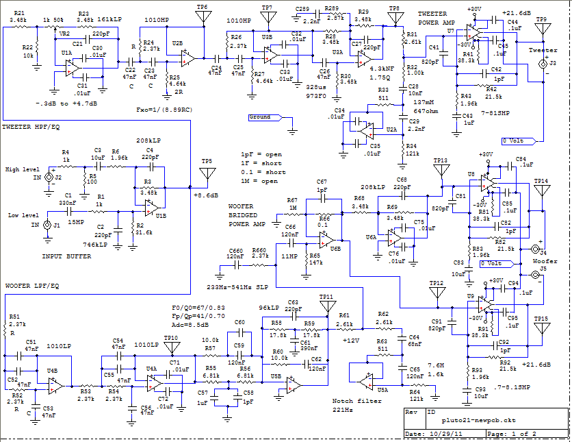
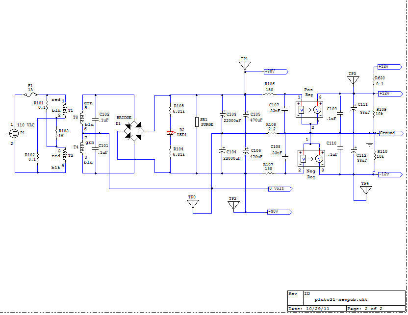
PCB Rev. 110111 A - Circuit schematic
A - Circuit schematic
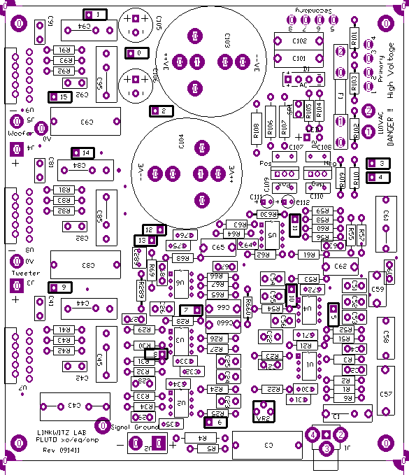
B - Component placement
C - Material listpluto21 material-newpcb-112311.xls Parts supply sources: DigiKey, Mouser, Newark, Allied, Jameco, Farnell, CALRAD, ZACK and others. Capacitor availability search at Mouser Capacitor availability search at DigiKey Agilent Technologies makes a U1701B Handheld Capacitance Meter ($158) for selecting capacitors to 2% or tighter tolerances.
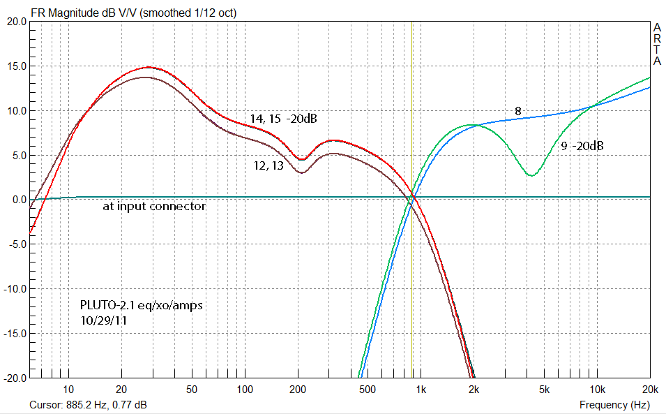
D - Input-to-output frequency response
E - Frequency response spot checksDerive output-to-input voltage ratios y = Vout/Vin
from the frequency response plots above. y = 10(Y/20) = 2.02 conversion from Y dB to its corresponding factor y Thus for a 100mV input Vin the output voltage at TP14 will
be Vout = Vin x 10 x 2.02 = 2020mV = 2.02V For the tweeter at TP8 and 10kHz the graph indicates Y =
10.3dB, thus y = 3.27. The resolution of the graphical reading is about 0.2dB. The curves are for a single prototype and carry within themselves the deviations of components from their nominal value shown in the circuit diagram above and how that affects the frequency response. A 2% or 0.17dB variation of a component does not affect the frequency response necessarily by the same amount. It depends upon where in the circuit and signal flow the component is located. To determine the uncertainty of the measured frequency response curves is not a trivial matter and requires a 'Monte Carlo' analysis of the circuit diagram, an analysis of the test method and of the instrumentation uncertainty.
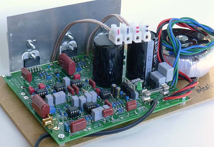
F - Mechanical constructionNote item --- (46) 1/16/09
PLUTO-2.1
Construction --- from the original Pluto owner support page.
G - Revisions23 November 2011 - Material list: Added 470uF. Corrected 10k resistor placement 6 November 2011 - First posting --------------------------------------------------------------------------------
|
|
| ||||