|
|
|
Recording & Rendering--- Recording
& Rendering 101 --- Acoustics
vs. Hearing
--- Subjective evaluation ---
Stereo Recording & Rendering - 101Definition of processes: 1 - Recording 2 - Rendering 3 - Reproducing
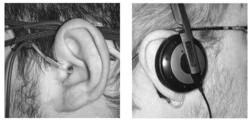
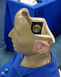
1.0 Binaural - Directly from eardrum to eardrum
1.1 Binaural in practice
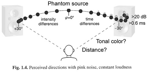
1.2 Quasi-binaural recording for loudspeaker playbackIt would seem natural that binaural recordings should work well for stereo loudspeaker sound reproduction. But the frequency response above about 3 kHz of the microphone pickup at the blocked ear canal is strongly determined by the shape and detail of the outer ear and the direction of sound incidence. This is the Interaural-Level-Difference, ILD frequency range of directional hearing. When this signal is reproduced over loudspeakers the response variations impart a coloration and misleading directional cues to the signals arriving from +/-300 at the listener's ears. Stereo recording microphones therefore have no pinna. The shape of the head and the distance between the ears causes sounds to arrive at the ears at slightly different times depending upon the direction of the sound source. Arrival times differ by less than 700 ms, which is used to give the brain directional cues in the Interaural-Time-Difference, ITD frequency range of hearing below 800 Hz. ITD and ILD are elements of the Head-Related-Transfer-Function, HRTF.
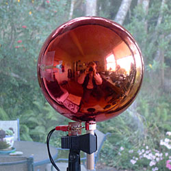
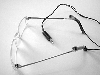
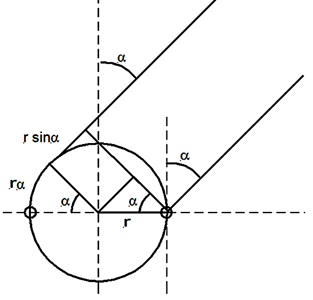
A sphere microphone preserves the spacing between the ears for low frequency sound localization and provides blockage of sound between the ears for the higher frequencies, Figure 3, [2]. I have used this microphone and a similar setup for my own head, Figure 4, to make recordings of events where I also then had a direct memory of what I heard. This gave me material to evaluate my loudspeaker designs. Sphere microphone are not optimal for rendering the recorded aural scene over two loudspeakers. The spacing between the microphones and the lack of low frequency directivity introduces misleading spatial cues in the ITD range of hearing and affects the realistic creation of phantom sources and aural scene. This will be shown below where loudspeaker stereo is explained. Top 2.0 From mono to stereo by panningStereo over two loudspeakers works by creating a phantom
acoustic scene between the loudspeakers. In its simplest form a single monaural
signal is fed to both left and right loudspeakers. If the two loudspeaker levels
are identical and there is no phase difference between them, then a listener on
the center line between the loudspeakers will hear the monaural sound as coming
from the center though there is no sound coming from that direction. This is
basically a very unnatural event and so a slight movement to the left or right
will shift the phantom source to the nearer loudspeaker. If the monaural signal
is artificial, like pink noise, then there will also be a change in tonal color
at certain off-center locations due to interference of left and right
loudspeaker signals at the ears. This has been called "the fundamental flaw
of 2-channel stereo" and a reason for promoting a center channel in 5.1
surround [3]. But surround has its own phantom source issues, between L and C,
between C and R and more.
2.1 Recording and rendering with paired microphones
Any pair of angled, coincident, directional microphones will automatically pan the recorded acoustic scene onto the line between left and right loudspeakers as a phantom scene. It will pan into left and right loudspeakers as monaural signals those portions of the +/-1800 view, which do not translate into phantom sources, because the microphone output levels differ too much. The monaural signals are problematic because they set hard boundaries to the phantom scene, which usually is not in keeping with the spread of the aural scene. It draws attention to the loudspeakers and their location, rather than letting the loudspeakers disappear from perception with eyes closed.
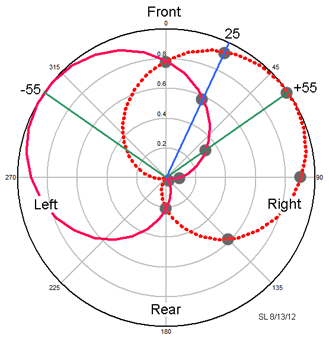
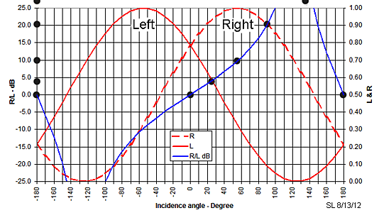
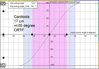
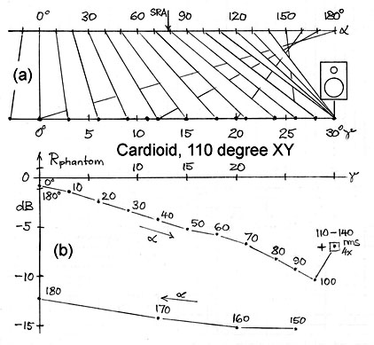
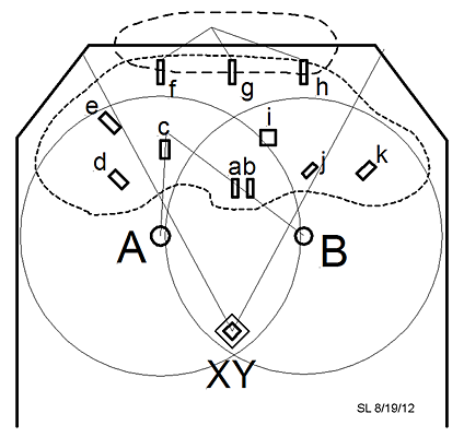
Different types of directional microphones arranged as XY coincident, as near coincident or spaced pairs will lead to a different distribution of the recorded acoustic scene on a standard +/-300 loudspeaker setup for reproduction, Figure 11. It is important to know the "Stereo Recording Angle" of a particular pair of microphones, because it determines which portion of the 3600 acoustic scene to be recorded will show up between the loudspeakers and with what linearity of distribution between the +/-75% points symmetrical to the center location. This has been calculated and catalogued with a JAVA applet following a panning law like in Figure 7, [6]. Results for a pair of cardioid microphones are shown in Figure 12.
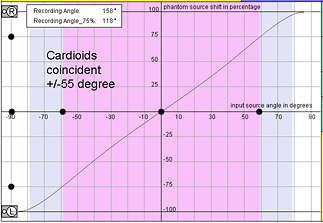
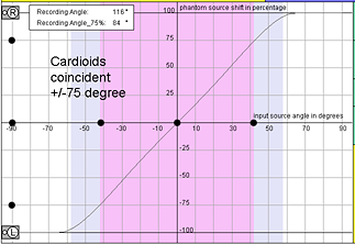
Fig. 12 Stereo recording angle for three different arrangements of cardioid microphone pairs. The phantom positions for the +/-550 coincident pair must have been derived from a different panning relationship than in Figure 7. At 250 incidence the phantom source is at 30% or 90 off center whereas from Figure 10 and Figure 7 it would be at 50% and 150. It should be noted that panning relationships have been determined empirically. Different investigators report different results, also depending upon source material. Directional hearing is a brain process and subjective. Nevertheless the graphs can show trends. Widening the angle to +/-750 places a narrower +/-420 section of the acoustic scene between the 75% points, whereas before it were +/-590. Separating the microphones by 17 cm leads to the well know ORTF arrangement. It further narrows the 75% rendered angle to +/-340. The graphs only cover the +/-900 frontal plane, not +/-1800 and elevation. It also cannot be deduced from them how recorded and monaurally rendered left and right loudspeaker signals might affect spatial perception. What exactly then are the aural differences between the three arrangements in Figure 12? The SCHOEPS Mikrofone website provides sound samples of recordings, which use the same recording angle, but where the types of microphone pairs differ [7]. In general, only an experienced recording engineer with adequate monitor loudspeakers might know how direct, reflected and reverberant sounds from various directions combine in a particular venue at the microphones and will be rendered over two loudspeakers. The monitor loudspeakers used, their setup and environment influence the decisions made by the recording engineer and limit the timbral, spatial and musical quality of the end product, if they impose their own signature or are not fully trustworthy for the task. Top
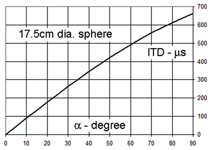
2.2 Rendering below 1 kHzHow does level panning, the sound of the same signal but at different levels from left and right loudspeakers, produce a phantom source between the loudspeakers? I call it a magic trick, because there is no sound-wave coming from the direction of the phantom source. The phantom source is a construct of the brain and based upon the signals at the eardrums. Below 1 kHz, where the wavelengths of sounds become large compared to the size of the human head, the ear signals differ very little in magnitude. But if the sound arrives from directions other than the vertical plane of head symmetry, then the ear signals contain a time difference. It is called interaural time difference or ITD and is a very strong contributor to directional hearing [8, 9]. Interaural level differences, ILD predominate above above 3 kHz where the head and outer ear dimensions become large compared to the wavelengths of sounds.
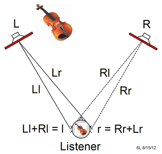
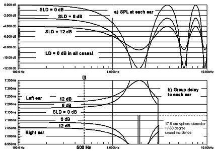
Each stereo loudspeaker sends its output to both left and right ears where they add as vectors, Figure 15. The phantom source direction, distance, size and sound are derived from the summed sound streams l and r. The frequency response for l and r shows that both ear signals have identical (!) magnitude, Figure 16a. Their level is maximum when L and R loudspeakers have the same output. The level decreases at both ears equally when one of the loudspeakers becomes louder and the other decreases while keeping L+R = constant [10].
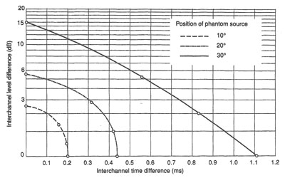
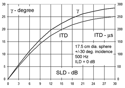
The ear signals differ in time of arrival, Figure 16b. ITD is directly related to SLD. Additional values have been calculated for a 500 Hz signal and are plotted in Figure 17 as a function of level differences between the loudspeakers. The ITD values are compared to those in Figure 14 for a real source. The comparison yields the phantom source angle g, which is thereby known as a function of SLD, [10]. Knowing the output signals and their ratios for a coincident pair of cardioid microphones, Figure 10, we can now derive the phantom source angle g for a given source angle a and the relative sound level of the phantom source, Figure 18.
If pure time panning is used, where left and right loudspeaker signals have the same magnitude and only differ in time, then the resulting ear signals have zero (!) time difference. The level at each ear changes in comb filter fashion with frequency and at a different rate for each ear depending upon the time difference. This produces a sense of spaciousness and maybe even a sense of phantom direction, but it is an unnatural phenomenon and peculiar to two loudspeaker stereo. Even near-coincident microphone recordings, as with an ORTF or a sphere microphone setup, would suffer from it to some extent in the ITD frequency range. In the ILD frequency range the listener's head shadows the +/-300 loudspeaker signals slightly, which reduces cross-talk and together with the outer ear shape allows for level differences between the ears. Phantom source direction is primarily based on transients in this range. Top
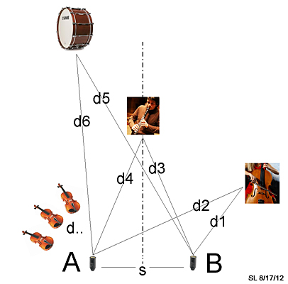
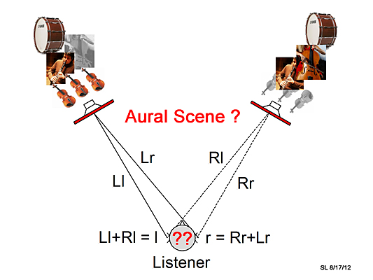
2.3 Spaced microphonesSpaced microphone recording techniques are prone to large amounts of leakage between sound pickups. In the case of spaced omnis each microphone sees the whole acoustic scene from a different location. Each microphone output emphasizes different sound sources due to greater proximity to one or the other, Figure 19. For example the cello is closer to microphone B than to A and its pickup will be [20*log(d2/d1)] dB stronger than from A. This ratio will also be modified by the frequency dependent directional radiation properties of the cello [11]. Furthermore the path length difference [d2-d1] causes the output from microphone A to be delayed by [2.9*(d2-d1)] ms/m. The sound stream produced by the cello in the output of microphone B can therefore differ significantly in magnitude and phase from that in microphone A.
The clarinet, which is at equal distance [d3=d4] from A and B will produce microphone outputs that still may differ in magnitude due to the directionality of clarinet sound radiation. The path lengths d5 and d6 do not differ much for the more distant drum, especially when compared to a wavelength, which is 3.4 m at 100 Hz. But since the drum is a dipolar radiator for many of its membrane vibration modes, it matters how it is facing A versus B. The strength and character of the sound pickup could vary depending upon the separation s between the microphones. The group of violins close to A will be distant in the microphone output B and of a different blend compared to their pickup from A. The two microphone signals A and B are transmitted to left and right loudspeakers. If we only turn on the left loudspeaker by itself, then we immediately localize the source of the sound as being the left loudspeaker. We are likely to hear that the sound is made up of sound streams from violins, clarinet, drum and cello when we listen for a while. We may develop a sense of how close those instruments were to the microphone and hear the reverberation of the venue when the drum is struck. Similarly when we only listen to the right loudspeaker we will hear the cello more clearly and distinct from the more distant violins. The clarinet may sound just the same. But what happens when both loudspeakers are turned on? Now we experience a phantom scene between loudspeakers and with spaciousness added. Localization becomes diffuse and when many more instruments are involved, tends to cluster around left and right loudspeakers with somewhat of a hole in the middle. Reversing the polarity of one of the loudspeakers will usually not change the aural scene. The problem is for the brain to decipher the two sound streams [Ll+Rl] and [Rr+Lr] into something meaningful [12]. Spatial hearing is a process that has evolved in humans over eons of time but there is little brain patterning for these types of sound streams. Still, very enjoyable recordings have been made with spaced microphones for 2-channel stereo. Here the recording engineer must find the location for the spaced pair that yields an aesthetically pleasing recording that does justice to the music's composition and the audience's expectations. Detailed spatial rendering is usually of low priority, also because many playback systems lack that capability. Top
2.4 Blending AB and XY recording techniquesInstead of using A and B microphones in Figure 19 to produce a 2-channel recording a single microphone could have been assigned to the violins, the drum, clarinet and cello for a 4-channel recording. Unless these microphones are placed very close to their individual instruments they will pick up low levels of all the other instruments and the reverberant sound in the venue. But if a microphone is very too close to an instrument it might pick up a sound that is modified by the directional characteristics of the instrument, that is unnatural and would normally not be heard by an audience [11]. All this can be avoided by placing each musician in an isolation booth and with headphones so he can hear everyone else to play in ensemble. Now we would have four sound tracks that can be level panned between left and right monitor loudspeakers to produce the 2-channel recording. Each track could even be panned multiple times. Violins, drum, clarinet and cello tracks have become sound objects that can be manipulated at will. The result is a collage of sound clusters that hang like sheets of laundry on a clothes line between the loudspeakers. Even when artificial reverberation is added to the mix the aural scene remains spatially flat and unnatural.
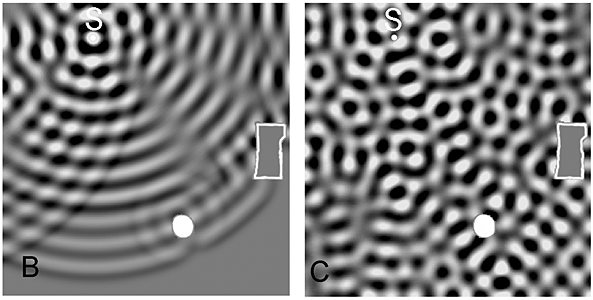
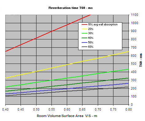
3.0 Rendering in a reverberant environmentListening to stereo usually takes place in an enclosed space. It means that the loudspeaker signal is reflected by walls and objects in the room not only once but again and again as it bounces around, Figure 22. The signal loses energy with each reflection. Very quickly the sound level in the room, away from the loudspeakers, becomes independent of listener location. That level is established by the rate at which acoustic power is fed into the room and the rate at which the reverberated sound is dissipated as heat by walls and objects. A listener very close to the loudspeakers will hear primarily the direct sound. At greater distance from the loudspeakers the reverberated and diffuse sound in the room dominates. It is louder than the direct sound at that location. The distance from the loudspeakers, at which direct and reverberant sound levels are equal, is called the reverberation radius or critical distance [13].
At low frequencies, where the wavelength of sound is no longer small compared to the dimensions of the room, the reverberant field takes the form of standing waves or room modes. As a consequence, the difference in sound level between two locations in the room can be very large at certain low frequencies. Rendering problems can be minimized by installing acoustic absorbers and/or minimizing the excitation of objectionable modes by woofer placement and/or directivity.
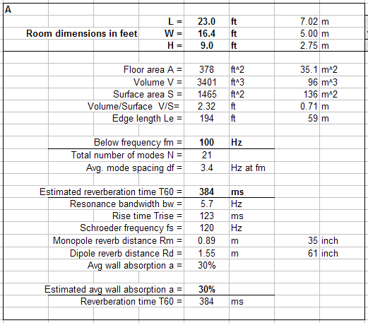
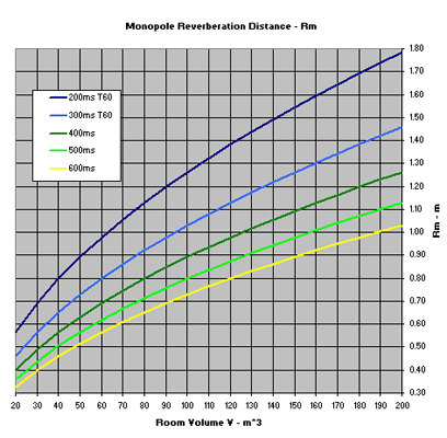
A reverberation time of 384 ms means that 30% (41 m2 or 440 ft2) of the room surface area behaves acoustically like open windows through which sound escapes. That is more than the floor area in size. A shorter reverberation time requires even more absorption. The direct SPL from the loudspeaker, which decreases as [1/distance], becomes equal to the reverberant sound level at 0.89 m, provided that the loudspeaker radiates like a perfect omni. The critical radius becomes 1.55 m for an ideal dipole because of its directivity of 4.8 dB.
If we wanted T60 = 250 ms for the above room, then the
average wall absorption would have to increase to 54%, Figure 24. This will take
considerable effort to achieve and the room will no longer be experienced as a
normal living room. A reverberation time of 250 ms is required by EU
Broadcasting Standards for recording studios. The benefit of reduced
reverberation time is an increase in reverberation radius from 0.89 m to 1.30 m
for the monopole and from 1.55 m to 2.25 m for the dipole, Figure 25. Typical
studio monitors radiate omni-directional from low frequencies up to several hundredth
of Hz. They become increasingly forward directional as frequency increases, when
baffle and radiator sizes become first comparable and then large in size
relative to the wavelengths of radiated sound. Thus the reverberation radius and
the ratio of direct to reverberant sound will increase with frequency compared
to the monitor's lower frequency interaction with the studio room. Statistical room parameters can be estimated from the
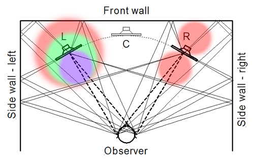
spreadsheet modes1.xls. 3.1 Loudspeaker placementThe reflective and reverberant environment of a room restricts the placement and radiation characteristics of the loudspeakers. The equilateral triangle, formed by the loudspeakers and the listener in a stereo system setup, must be placed symmetrical to the room boundaries or large objects in the room, Figure 26. This ensures symmetry of the reflections relative to the center axis and a sharply defined center phantom image for monaural loudspeaker signals or center panned sounds. Each loudspeaker also must be placed at some distance from front and side walls so that reflections reach the ears later than the direct loudspeaker sounds. In that case the brain can filter out the direct sound streams more readily from those due to reflection and reverberation. A minimum time gap of 6 ms between direct and reflected sounds is needed, which translates to a minimum distance of 1 m from the walls.
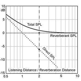
Furthermore, reflected sounds should be spectrally coherent with the direct sound to a high degree for unambiguous perceptual processing. Direct and reflected sounds then generate a reverberant sound field that is spectrally coherent with the direct sound at the listener's ears [14, 15, 16]. Under those conditions a listener can withdraw attention from the room and focus on the aural scene in front of him. Room and loudspeakers disappear. Coherence of the room sound requires a frequency independent polar response of the loudspeaker. It implies a constant directivity loudspeaker such as a monopole, dipole or cardioid. Experience has shown that the optimum listening distance should be less than twice the radiation radius so that the direct sound is less than 6 dB below the reverberant sound level in the room. In the example of Figure 23 that should be less than 1.8 m (6 ft) for the monopole or 3.1 m (10 ft) for the dipole source. The maximum recommended loudspeaker spacing would become 6 ft for the monopole or 10 ft for the dipole. The dipole reaches deeper into the room because it interacts less with it. Top
4.0 SummaryThe type and performance of loudspeakers used, their setup, the listening distance and the room's acoustic properties determine the quality of the rendered aural scene at the consumer's end of the acoustical chain. The aural scene is ultimately limited by the recording. The type and configuration of microphones used, their setup, the venue, the monitor loudspeakers for the mix, their setup, the listening distance, the studio's acoustic properties and the mix determine the quality of the recording at the producer's end of the acoustical chain between performer and consumer. Monitor and consumer loudspeakers must exhibit close to
constant directivity at all frequencies in order to obtain optimal results for
recording and rendering.
5.0 References[1a] David Griesinger, Frequency Response Adaptation in Binaural Hearing, 126th AES Convention, Munich 2009, Preprint 7768, www.davidgriesinger.com [1b] David Griesinger, Binaural Hearing, Ear Canals, and Headphone Equalization, PowerPoint presentation [2] Joerg Wuttke, Zwei Jahre Kugelflaechenmikrofon, Mikrofonbuch_Kap5.pdf, 1992, https://www.schoeps.de/en/information [3] Floyd E. Toole, Sound Reproduction, Focal Press, 2008 [4] Peter Damaske, Acoustics and Hearing, Springer, 2008 [5] Francis Rumsey, Spatial Audio, Focal Press, 2005 [6] Helmut Wittek, Image Assistant, JAVA applet for determining the "Stereo Recording Angle", www.hauptmikrofon.de [7] SHOEPS Mikrofone, Showroom, www.schoeps.de/en/applications/showroom [8] Jens Blauert, Spatial Hearing, The MIT Press, 1997 [9] Eric Benjamin, An experimental Verification of Localization in Two-Channel Stereo, 121st AES Convention, San Francisco 2006, Preprint 6968 [10] Siegfried Linkwitz, A Model for Rendering Stereo Signals in the ITD-Range of Hearing, 133rd AES Convention, San Francisco 2012, Preprint 8713, Abstract, Presentation slides [11] Juergen Meyer, Acoustics and the Performance of Music, Springer, 2009 [12] Albert S. Bregman, Auditory Scene Analysis - The Perceptual Organization of Sound, The MIT Press, 1999 [13] Heinrich Kuttruff, Room Acoustics, John Wiley & Sons, 1973 [14] Siegfried Linkwitz, Room Reflections Misunderstood?, 123rd AES Convention, New York, October 2007, Preprint 7162, Manuscript, [15] Brad Rakert, William M. Hartmann, "Localization of sound in rooms. V. Binaural coherence and human sensitivity to interaural time differences in noise", J. Acoust. Soc. Am., Vol. 128, No. 5, November 2010 [16] William M. Hartmann, Signals, Sound, and Sensation, Springer, 2005 SL - 21 August 2012
See also: Links - Introduction to Sound recording Recording & Rendering - 101 can be downloaded as PDF
===========================================
|
|
| ||||