|
|
|
Recording & Rendering--- Recording
& Rendering 101 --- Acoustics
vs. Hearing
--- Subjective evaluation ---
Sound Field Control for Rendering Stereo - 1Creating a believable Auditory Scene using two loudspeakers in a reverberant room
Siegfried Linkwitz
Sound Field Control for Rendering Stereo - 2The following was written for the AES 52nd International Conference, "Sound Field Control, Engineering and Perception", Guildford, UK, September 2013. The manuscript was accepted and the presentation scheduled, but I cannot attend the Conference due to conflicting family events. I withdrew the manuscript and now publish it reformatted on my website.
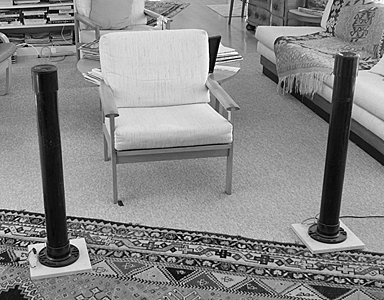
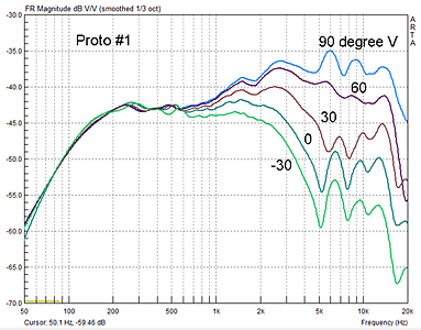
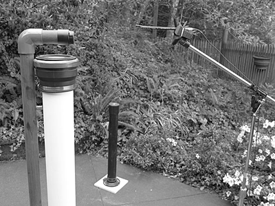
ABSTRACTStereo program material reproduced over two loudspeakers creates an aural scene in the listener’s mind. The phantom scene usually appears to originate at and behind the line between the loudspeakers. The perception is derived from cues in the direct sound streams from each loudspeaker and from room reflected and reverberated sound streams. Ideally, the loudspeakers and the listening room are not heard as such. It has been found that reflected streams and reverberation must carry the same spectral content as the direct streams and that first reflections must be delayed by proper placement of the speakers. The loudspeakers must be designed for frequency independent directional behavior. Practical approximations are shown for a monopole and a dipole constant directivity loudspeaker. Limitations to radiation pattern and sound output capability due to driver and baffle dimensions are discussed. INTRODUCTIONVisual inspection shows that the vast majority of loudspeakers, which are currently sold for use in domestic stereo or home theatre set-ups, are designed with only minor attention to their off-axis radiation behavior. The target is usually a flat on-axis frequency response. In some cases the response is specified within certain dB limits throughout a rectangular listening window of +/-300 horizontal and +/-100 vertical width. In even fewer cases the power response and directivity index are specified or controlled. A change in directivity from 0 dB below 200 Hz to over 10 dB above 10 kHz is normal. Such loudspeakers are omni-directional at low frequencies and become increasingly forward beaming for higher frequencies. On-axis and off-axis radiation causes room reflections, excites room modes and determines the strength and timbre of the reverberant sound field. A listener’s perception of the phantom acoustic scene between the loudspeakers depends upon the ratio of direct sound streams coming from the loudspeakers at +/-300, to the room modified indirect sound streams arriving at a multitude of angles of incidence and all summing at the ears. In a highly damped room with RT60 < 250 ms, as in a recording studio, the reverberated sound field is weak and becomes perceptually insignificant under close-field monitoring conditions. Common domestic size living and listening spaces have reverberation times of >400 ms. The optimum listening distance can become inconveniently short. The typical box loudspeaker radiates too much power at low frequencies, feeding room modes disproportional to the power in the reverberant field at higher frequencies. Optimal conditions for phantom source perception are obtained when a) the room reverberated sound streams have the same spectral content as the direct streams, when b) the first reflections are delayed by >6 ms, and when c) the ratio of direct to reverberated stream levels is greater than –6 dB. Under those conditions the listener’s brain can withdraw attention from room and loudspeakers and focus on the cues in the direct sound. A pair of loudspeakers with frequency independent radiation pattern, placed >1 m from large reflecting surfaces, set up in an equilateral triangle with the listener and symmetrical with the room boundaries, can provide a remarkable stereo phantom scene with fine spatial detail and believability. The requirements for optimum rendering of stereo have not been explicitly stated in the literature, nor fully investigated, but many pointers have been provided over the last six decades. For example see references [1-20]. 1. CONSTANT DIRECTIVITY LOUDSPEAKERSBasic models for loudspeakers with frequency independent radiation pattern are the monopole, cardioid and dipole. The monopole interacts maximally with the room. Any practical monopole is constructed from sub-enclosures, which decrease in size with increasing frequency, in order to remain acoustically small, while providing the necessary volume displacement for loudness. A cardioid loudspeaker requires an acoustic flow resistor for its operation unless it is realized by combining a monopole and a dipole radiator. To build a broadband and linear acoustic flow resistor for low frequency reproduction can be difficult. Also, internal cavity and panel resonances can cause spurious radiation similar to a monopole. A cardioid would not illuminate the wall behind it with direct sound, but has the same overall sound output into the room as a dipole with the same on-axis SPL and has therefore an identical Direct-to-Reverberant ratio at the listening position. Compared to a monopole the D/R is 4.8 dB higher. This also means that the reverberation time of the room could be three times higher for the same D/R ratio as from a monopole. It is a significant advantage for the dipole or cardioid radiator. In a typical domestic room with RT60 = 500 ms their reverberation distance is the same as for a monopole in a highly damped room with RT60 = 167 ms. Here RT60 refers to the frequency range above the Schroeder Frequency of around 150 Hz [2]. A dipole radiator is the most practical solution for a constant directivity loudspeaker provided that its baffle dimensions are acoustically small and the radiating elements are tightly positioned together in a vertical line. Dipole loudspeakers in the form of large planar electrostatic or magnetic radiator panels, tend to suffer from multi-beam radiation due to acoustically large radiating surfaces and from insufficient output volume at low frequencies. Size and output problems can be overcome by using conventional piston drivers with appropriate cone diameter and large excursion as radiating elements. Design and construction of constant directivity loudspeakers has its difficulties and tradeoffs must be made as with all loudspeakers. Radiation in the vertical direction is usually restricted in favour of controlled horizontal dispersion. In the following we present design issues for a small experimental monopole radiator, a higher output monopole and a state-of-the art dipole. 1.1 Monopole - CD Proto #1The loudspeaker is formed by a 75 mm diameter driver in a 100 mm diameter coupler at the top of a ABS pipe, which is sealed at its bottom (Figure 1). The correct amount of absorbing material on the inside of the pipe minimizes reflected signals being transmitted through the cone and provides sufficient internal volume to keep the driver’s mechanical resonance low. The high stiffness of the pipe suppresses spurious sound radiation from its surface. The frequency response in the horizontal plane is independent of azimuth angle due to axial symmetry of the radiator. The frequency response in the vertical plane (Figure 2) is independent of elevation angle below 700 Hz, but varies considerably at higher frequencies due to diffraction and the inherent frequency response of the driver.
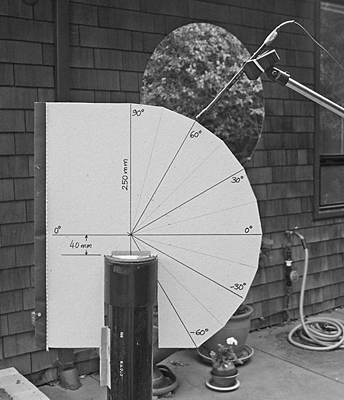
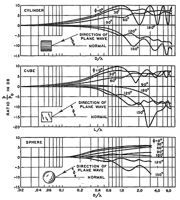
The acoustic center for vertical radiation is positioned 40 mm above the top plane of the driver (Figure 3). The microphone must be rotated around this point for the measured low frequency response to become independent of elevation angle [21]. The vertical response follows to some extent the general pattern given by a point source at he end of a cylinder (Figure 4, top). This type of radiator is not a true monopole, like an acoustically small pulsating sphere, but it follows its response in the horizontal plane and to a lesser degree in the vertical plane.
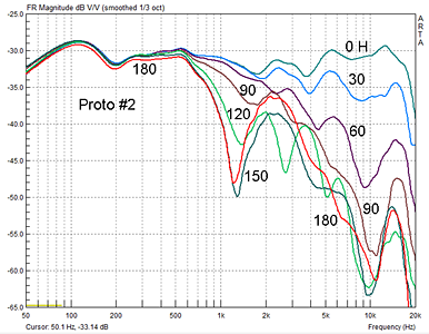
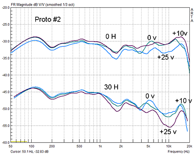
A pair of loudspeakers like this provides excellent spatial rendering even without equalization of the colored response. Imaging is precise and the sweet spot is very wide. The speakers must be listened to from a close distance to preserve detail in the phantom scene and because their maximum output volume is sufficient for voice but not for music program material [23]. 1.2 Monopole - CD Proto #2The limited output volume of Proto #1 is overcome by using two drivers to cover the frequency range, an upward firing woofer/midrange unit of 115 mm cone diameter and a forward firing 38 mm tweeter (Figure 5). The tweeter is mounted forward of the woofer axis to minimize diffraction. Using electrical delay the tweeter’s acoustic center is moved back to the woofer axis for signal addition in the +/-1 octave overlap region between drivers of the 1 kHz LR4 crossover. The frequency response in the horizontal plane (Figure 6), halfway between woofer and tweeter, measured at 0.3 m from the woofer axis, is independent of angle from 0 degree to 180 degrees below 500 Hz.
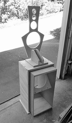
The speaker behaves like a pulsating sphere below 500 Hz and gradually turns into a forward firing radiator with wide vertical and horizontal dispersion as frequency increases. The speaker has proven itself as a neutral radiator in a reverberant space, rendering precise phantom image detail and dynamics when listened to at less than twice the reverberation distance for a monopole in the specific space [24]. 1.3 Dipole - CD Proto #3Experience has indicated that a full range and acoustically small dipole loudspeaker must be designed as a 4-way radiator. Dimensions for the woofer are easily kept small but this requires very high volume displacements from the drivers. For example, the woofer section can produce a sound pressure level of 94 dB at 30 Hz and 1 m distance when placed on a reflective ground plane. This requires a peak-to-peak volume displacement of 2000 cm3 and front-to-back distance of the open baffle of Dd = 400 mm. [25] The same 94 dB SPL is generated at 120 Hz by a much lower 31.25 cm3 p-p volume displacement, if Dd = 400 mm. But maintaining dipole behavior over the midrange from 120 Hz to 7 kHz becomes difficult, because front-to-back distance Dd, driver size and baffle dimensions become first comparable and then larger than the radiated wavelength. Two differently sized drivers and a uniquely shaped baffle were needed to cover such wide frequency range. 1.3.1 Dipole baffle
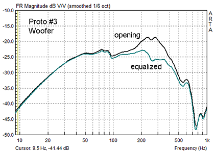
1.3.2 Dipole woofer
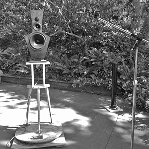
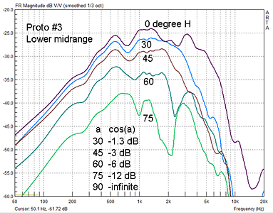
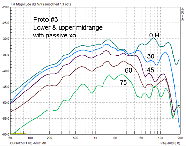
1.3.3 Dipolar lower and upper midrangeThe polar response of the top baffle is measured from 0.5 m distance in the backyard, being elevated and positioned on a manual turntable (Figure 10). The lower midrange driver exhibits close to textbook behavior up to about 1 kHz (Figure 11). The baffle shape was determined empirically. Only frontal radiation is measured. Rear radiation reaches the listener via room reflections and reverberation, which makes the details of the response much less important. The total power radiated to the rear must be similar to the total power radiated to the front hemisphere.
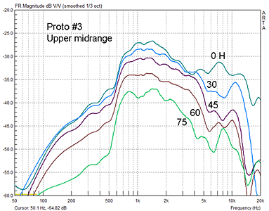
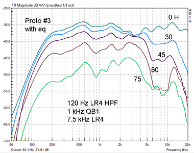
The upper midrange driver with its narrow baffle is well behaved above 1 kHz (Figure 12). The response widens between 00 and 300 around 3.5 kHz but is in general quite useable up to 10 kHz. When the two drivers are combined with a passive quasi-B1 crossover at 1 kHz, i.e. a crossover that is 6 dB down at 1 kHz and provides in-phase addition, then the resulting overall response indicates dipolar behavior over a very wide frequency range (Figure 13). The widening around 3.5 kHz depends upon the vertical position of the measuring axis. Here it is the upper midrange driver axis. In general, it would take many sets of measurements to fully describe the polar radiation details when the vertical distances between drivers and the baffle dimensions are no more acoustically small.
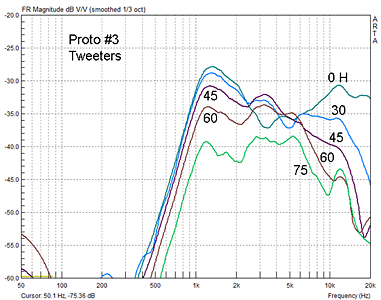
1.3.4 Dipolar tweetersRadiation from front and rear tweeters
interacts in space forming a radiation pattern with sound cancellation in the
plane of the baffle and a dipole like angular dependency (Figure 14). Below 2
kHz the baffle is acoustically small and a true dipole response results.
Dispersion widens with increasing frequency, which is normal for a fixed baffle
size. Above 5 kHz the inherent directivity of the dome drivers takes over. Front
and rear radiation only interact at large off-axis angles.
2. SUMMARYSound field control is essential for optimum stereo rendering, because it determines how the listening room is illuminated with sound by the loudspeakers. The radiation pattern must be frequency independent for the loudspeaker to leave no signature of its own in the room, which would compete with the phantom scene to be created in the listener’s mind. Practical difficulties and trade-offs in designing for constant directivity have been illustrated with three prototypes. Never the less, the last two examples can demonstrate what the simple stereo format is capable of in terms of spatial rendering and realism when misleading cues from loudspeaker and room are minimized. One can only hope that the importance of sound field control for home stereo systems becomes widely recognized, that novel loudspeakers will become available and that the generic box loudspeaker sound and room problems are relegated to the past. 3. REFERENCES*** L. L. Beranek, T. J. Mellow, Acoustics - Sound Fields and Transducers, Elsevier (2012)
***************************************************************************************************
See also:
|
|
| ||||