
| Build-Your-Own | Main Panel
| Dipole Woofer | Crossover/EQ
| Supplies |
| System Test | Design Models
| Prototypes | Active
Filters | Surround | FAQ
|
You may not be familiar with the sonic benefits of open
baffle speakers from direct experience and therefore hesitate to launch into
building the PHOENIX. After all, such project would take a major commitment of
your time and money. Instead, you might want to try first a less costly design,
but something still indicative of what ultimately can be achieved.
To this purpose I describe a dipole woofer of easy H-frame construction, and a
small dipole 2-way speaker that uses very economical drivers and a passive
crossover. Equalization of the 6 dB/oct dipole roll-off, and a woofer to
midrange crossover filter, is accomplished with line level
resistor/capacitor networks, connected between preamplifier and power amplifier.
This avoids dealing with active electronics, but requires considerably higher output
voltage from the preamplifier to compensate for the insertion loss of the
networks.
A - Open-baffle woofer - PW1
B - Woofer crossover to existing midrange - PXM1
C - Mini open-baffle speaker - PMT1
D - Main panel with passive crossover to tweeter - PMTM1
E -
Crossover/Equalizer for passive dipole
woofer
F - Transition to fully
active systems
G - PA column loudspeaker
A - Open-baffle woofer - PW1

H-frame woofer, 27x14x16 inch, with 12" Peerless XLS
830500 drivers.
The woofer cabinet is essentially only a sound barrier
between the output from the front and rear radiating 12" drivers. The
sketch below shows the cabinet dimensions in inch. Construction materials
are not critical. You may want to add mass on top or bottom of the cabinet to
reduce its movement, which is caused by the force of the drivers' moving masses.
The movement is not critical as long as it is non-resonant, because the
radiating surfaces are small and act as dipoles. Also, place the cabinet on felt
pads to avoid rattles. Two of these woofers are need, since otherwise output and
distortion performance are marginal.
At the opening of the cabinet you can measure a frequency
response that has not been affected by dipole cancellation, because the
microphone is so close to the source. As you move the microphone away, the
response will decrease progressively as frequency goes down and more of the rear
output cancels the sound at the microphone. This must be equalized to obtain a
flat woofer response.
The woofer is equalized only down to 30 Hz to limit cone
excursion demands. Below 30 Hz and below Fs of the driver the response
ultimately approaches an 18 dB/oct roll-off slope.
At 100 Hz a 2nd order L-R lowpass filter forms one half of the crossover to the
midrange. The desired acoustic response is controlled closely by the electrical
network. Thus, a variety of 12" drivers can be used with the network.
Not equalized are the driver roll-off behavior as determined by Fs and Qt and
the air cavity resonance around 250 Hz. Different options for the midrange
crossover highpass
filter will be shown below.
The woofer crossover/eq response is obtained from a
passive line level network between preamplifier and power amplifier. The
disadvantages of this solution are 1) a high insertion loss, and 2) the exact
transfer function can only be approximated.
The insertion loss can be compensated with a higher volume setting on the
preamplifier, if it is capable of the necessary voltage swings at the required
playback volume level.
Using only resistors and capacitors in the network and no inductors leads to the
approximation of the transfer function. Inductors would be impractical, because of the large
values needed for the high impedance levels that must be used at the
preamplifier to power amplifier interface.
It is important that the input
impedance of the power amplifier is 10k ohm, otherwise all network impedances
must be scaled proportionally to its different value to stay close to the
targeted response.
An active circuit with the target response and 0 dB insertion loss is shown in w-xo-lp2.gif
for comparison and may become a better solution if the preamplifier has
insufficient output. A circuit with this type of response can be
constructed using one of my general topology printed
circuit boards. - Top
B - Woofer crossover to existing midrange -
PXM1
The woofer equalization network above already includes a
100 Hz, 12 dB/oct lowpass filter for the acoustic crossover to the midrange. On
the midrange side a 12 dB/oct acoustic highpass filter is need. There are
several possibilities.
1 - The midrange happens to exhibit the correct acoustic highpass behavior, is 6
dB down at 100 Hz and falls off at 12 dB/oct, which means it is some closed box
speaker. In that circumstance no electrical filter is required and only the
level to the midrange power amplifier has to be adjusted relative to the woofer
amplifier. Since the woofer xo/eq has no gain, but the low frequency output of
the dipole woofer has to be boosted relative to the midrange, an adjustable
attenuator must be placed ahead of the midrange amplifier. This can simply be
the attenuator section (5.11k - 5k pot - 1k) of the circuit below.
2 - The midrange frequency response happens to be almost flat to 50 Hz or below
as maybe for a small monitor. In that case the midrange unit will primarily add
phase shift at a 100 Hz, but little amplitude change. Now the line level network
below can be used. The extra phase shift adds a certain amount of delay which can
be compensated for by positioning the midrange forward of the woofer.
An active circuit with the target response and 0 dB insertion loss is shown in m-xo-hp2.gif
for comparison and may become a better solution if the preamplifier has
insufficient output. A circuit with this type of response can be constructed
using one of my general topology printed circuit boards.
3 - Neither of the two cases above apply. You might try a
single capacitor in conjunction with the variable attenuator to form a 6 dB/oct
highpass, if the midrange exhibits already some roll-off at 100 Hz.
This might be a situation where full equalization of the midrange highpass
behavior becomes necessary. An active circuit
(biquad) allows to shift the poles in the midrange response to the desired
crossover frequency. A circuit with this type of response can be constructed
using one of my general topology printed circuit boards.
-
Top
C - Mini open-baffle speaker - PMT1
There is a practical limit to the smallest size of an open
baffle speaker, if it is expected to reproduce a balanced full range sound
spectrum. The PMT1 represents this case. The speaker might be used for a stereo
system in a small room or for side and rear speakers in an audio surround setup.
I have little experience with home theater, but expect that it would perform
especially well as a center speaker, because of its well behaved and wide polar
response. The lack of magnetic shielding might be an issue.
The design is a 2-way loudspeaker with a passive crossover
between a Vifa P21WO-20-08 woofer and a Vifa D26TG-35-06 soft dome tweeter. I am
sure some of you have preferences for different drivers and so you might use
this design as a starting point for your own experimentation. An alternative
tweeter could be the silk dome D27TG-45-06, but I have observed some variability
with the supplied units.
The cabinet design follows the concepts of the PHOENIX
main panel. The dimensions are slightly different to reduce size. The hole
cutouts and recesses must be adjusted to the Vifa drivers and the gasket
materials used.
The on-axis frequency response shows the inevitable dipole roll-off at 6
dB/oct towards low frequencies. To maintain perceived spectral balance the high
end is rolled off slightly to compensate for the low end behavior. It is
possible to use some low frequency equalization, but as this increases the cone
excursions, the 8" driver will sooner begin to distort.
A line level equalization down to 50 Hz is shown below. Again, it comes at the
expense of high insertion loss and greater demands on the preamplifier output
capability.
Note, if this speaker will be used with separate woofers,
ideally dipole woofers, then you want to avoid the compensatory high frequency
roll-off. Use a slightly different midrange/tweeter crossover and add a
crossover of your own design for midrange and woofer. This is best accomplished
actively, since the woofer already requires active
equalization.
Reversal of the tweeter polarity and the ensuing depth of the notch indicate the
accurate addition of midrange and tweeter output through the crossover region in
normal mode.
The passive crossover is relatively simple, though unusual for the midrange
as it corrects for some of the dipole behavior. The 3.3 mH inductor should have
low DC resistance (<0.2 ohm). The 48 uF capacitor can be formed by the series
connection of two 100 uF electrolytics (Panasonic HF-Series). The terminal
impedance has a minimum of 5 ohm between 100 Hz and 200 Hz.
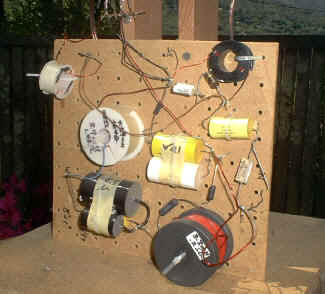 Quick
and messy looking crossover. The electrons don't mind as long as the fields
don't couple.. Quick
and messy looking crossover. The electrons don't mind as long as the fields
don't couple..
The line level equalizer below uses a bridge type network
to increase the rate of frequency response change around 200 Hz. This avoids
causing a bump in the speaker output response.
The identical frequency response could be obtained with an
active network, but since equalization is of questionable value due to cone
excursion limitations, I will not present it. The PMT1 speaker should only be
used where its somewhat limited output capability is acceptable. There it will
show the benefits of the box-less approach, namely open, uncolored and
transparent sound reproduction.
----------------------------------------------------------------------------------------------------------------------
Letter from a PMT1 builder
----- Original Message -----
From: "Bruce Coppola" <bcoppola1@comcast.net>
To: "Siegfried Linkwitz"
Sent: Thursday, September 08, 2005 7:34 AM
Subject: More thoughts on the PMT1
Siegfried;
Even though I'm building and looking forward to the Orions, I had to
share
some more thoughts on the PMT1s after living with them for nearly two
years.
They are splendid little speakers in their own right. In fact, a lot of
what
that Pluto builder said in his recent review applies to the PMT1s. Good
recordings sound great; lesser recordings have their flaws revealed. Well
recorded music is invariably involving. Listening fatigue is not an issue.
Bass is natural and articulate, as well as deep enough for most music. For
a
small room, the PMT1s are probably the equal of many highly regarded
two-way
small monitors that cost thousands. Your stated caveats about the design
all
apply, of course. But they apply to lots of those good commercial
small
speakers too.
Frankly, sometimes I find myself wondering how much better the Orions can
be, except for dynamic capability and bass extension.
You said you've "dotted the I's and crossed the t's", but if
you're inclined
one day maybe you could make a PCB available for the PMT1 passive
crossover
(with off-board connections for the big inductors). It might make them
more
accessible to more builders, thus introducing more people to the dynamic
dipole concept. More ambitiously, maybe you could work out an active EQ
that
would avoid excessive woofer excursion (with a high pass filter at 50 hz
or
so?). I wish I had the technical ability to experiment with that on my
own.
I have a friend who is a recording engineer here in Detroit. He has
commented very favorably on my speakers, especially on the natural quality
of their bass. He told me that they were the only DIY speakers he's ever
heard that he didn't have to "nod politely and smile about". He
is very keen
on hearing the Orions when they're built.
You can quote all the above on your site if you wish.
--
Bruce Coppola - bcoppola1@comcast.net
https://www.bruce.coppola.name
O how full of briers is this working day world!
|
Top
D - Main panel with passive crossover
to tweeter - PMTM1
This prototype uses the same main
panel as the PHOENIX except for slightly different hole diameters, recesses
and spacing of the spine to accommodate two Vifa P21WO-20-08 and a D27TG-45-06
driver. The crossover between midrange and tweeter is passive to avoid an
additional power amplifier and active line level electronics. The response is
equalized to 50 Hz at the low end with a passive line level network as for the
PMT1 above. No additional woofer is required, if the system is used in small
rooms and at moderate sound levels.
Different drivers could be employed, but the component values in the crossover
will have to be revised to compensate for differences in terminal impedance,
sensitivity and frequency response. I leave such experimentation up to you, and
if you learn something exciting, please let me know.
Starting with a measurement of the drivers on the baffle,
you notice that the midrange slopes down towards lower frequencies from a peak
at 400 Hz. To remove the peak and to move the roll-off an octave lower, the
crossover must attenuate the signal seen by the 8" drivers. This in turn
requires that the tweeter highpass filter has insertion loss to match its
acoustic output level with that of the midrange.
The midrange lowpass filter in the crossover has an
unusual topology to correct for the peak and extend the flat region of the
response. The dc resistances of the two coils in the lowpass section are
included in the
resistor values shown.
The necessary electrical driving voltage response is measured
across the driver terminals. The slopes of the midrange and tweeter filters are
different. The steeper slope for the tweeter provides additional phase shift in
the crossover region to delay the electrical signal and to bring the acoustic
output in phase with the midrange.
Since the tweeter is mounted forward of the midrange the
added electrical delay gives better summation of the two acoustic outputs. The
graph below shows the on-axis response. To obtain an idea about the very
important off-axis behavior of the PMTM1 review the response curves for the PHOENIX on the
System Test page.
The low frequency response can be extended with the same
passive line level equalizer network as for the
PMT1 speaker above. For a closer look at the corrected response the time
data record for the FFT is increased to 120 ms. The resulting frequency response
is no longer anechoic and includes reflections from surroundings of the outdoor
test site. The ripples in the response are an indication of this and may have
been caused by objects as far as 60 feet away.
Equalization with the simple circuit is not completely
effective, because the roll-off is not only due to the 6 dB/oct dipole behavior,
but also due to the low Qts (~0.33) of the 8" drivers at their 30 Hz
resonance. The compound slope is steeper than 6 dB/oct.
A simple active line level equalizer avoids
the high insertion loss, large output voltages from the preamplifier, and the
10k amplifier input impedance requirement of the passive network. A more
complicated circuit could be used to
to push the influence of the 8" driver parameters to a lower frequency.
Since this also increases cone excursion demands it is more appropriate to use a
separate dipole woofer. A circuit with the desired response can be
constructed using one of my general topology printed
circuit boards.
The crossover input impedance is greater than 7.5 ohm at
all frequencies and an easy load to drive for a solid state power amplifier. The
impedance peak at 500 Hz can be leveled with a R-L-C
Zobel network at the input of the crossover. Also, a R-C
network might be added to terminate the speaker cable into 10 ohm for
frequencies above 50 kHz. Otherwise the cable might act as a resonant antenna in
the AM frequency band. Strong radio signals applied to the output of the power
amplifier can lead to a degradation of sound quality in some circumstances. - Top
A passive crossover with built-in 6 dB/oct equalization
can be approximated with a simple L-C lowpass network. A potential problem is
the low impedance that this circuit presents to the power amplifier. A
surprising number of amplifiers have difficulty to drive sufficient current into
such load. The 10 mH inductor must have very low resistance and a laminated
steel core to keep distortion low and avoid saturation.
Used with PHOENIX or H-frame
style woofers the XO/EQ can provide frequency extension down to about 40 Hz for the PMTM1.
Such fully passive crossover, 3-way open baffle speaker requires a solid-state
amplifier capable of delivering at least 75 W into 4 ohm simultaneously to both
channels. Active, line-level equalized woofers would require their own
amplifiers, but have much less serious power demands. - Top
F - Transition
to fully active systems
In addition to the active equalization of the PMTM1
low frequency response, the crossover to the tweeter could be made active.
Further, with an active crossover to the PW1 dipole woofer, the PMTM1 will turn into a lower cost
version of the PHOENIX (FAQ7, FAQ11).
The woofer may be needed to reduce distortion due to large excursions
of the 8" drivers when more bass output level is desired.
All the necessary electronics for such systems are laid
out on the
PHOENIX printed circuit board. Only some of the component
values need to be adjusted for different drivers or a 2-way configuration. Using the PHOENIX
active crossover/eq topology also makes it easy for you to experiment with
completely different models and
makes of drivers for either a 2-way or 3-way system. Alternatively, you could
use my general topology printed circuit boards to
build your own desired configuration. - Top
| Build-Your-Own | Main Panel
| Dipole Woofer | Crossover/EQ
| Supplies |
| System Test | Design Models
| Prototypes | Active
Filters | Surround | FAQ
|
| 


