
|
|
|
|
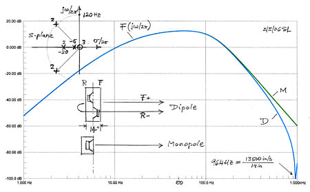 |
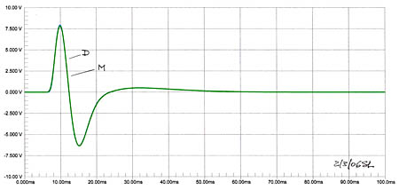 Dipole and monopole impulse responses for the frequency responses on the left are indistinguishable from each other. |
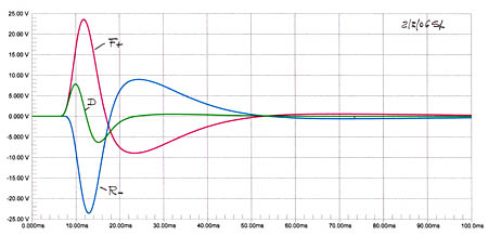
The dipole responses above are obtained by summing front and rear H-frame woofer outputs at a large distance. It is interesting to look at the actual outputs at front and rear openings of the frame. At these locations the frequency response is boosted by 6 dB/oct relative to the far-field response of the dipole and relative to that of an equivalent monopole. Thus the impulse response at front and rear openings has significantly larger amplitude than the impulse response of the monopole and is different in shape. These are the outputs of a far-field equalized dipole source as described by two spaced monopoles which are 180 degrees out-of-phase.
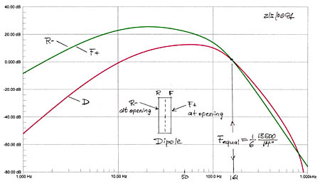 |
 Dipole in the form of two spaced monopole sources of opposite polarity when equalized for far-field. |
When I equalize an H-frame woofer I measure its response outdoors, sitting on a large concrete surface and with the microphone in the center of the front or rear opening plane. At this time no 6 dB/oct dipole equalization is applied so that I can measure the eventual far-field response with this microphone placement and adjust the response to my requirements. Applying the 6 dB/oct low frequency boost then turns it into the far-field response of the woofer.
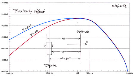 |
The response from a monopole source decreases as one-over-the-distance in free-space. Thus the front and rear monopole sources of a dipole undergo different amounts of attenuation when observed from a distance where the difference in distances is no longer negligible. For example, at 7 feet (84" = 2.13 m) on-axis from the source the difference in sound attenuation is 91"/77" = 1.18 or 1.45 dB. The rear output has become less effective in canceling the front output. This increases the woofer output as frequency goes lower. It is a "proximity effect". |
The above comparison between dipole and monopole woofers was under free-field conditions. When placed in a room the resulting sound field becomes difficult to analyze and the perceived audible differences between the two types of sources become difficult to explain, though they have been frequently described subjectively. Since a dipole source consists really of two spaced monopole sources of opposite polarity, it generates a large particle velocity between them and a local acoustic field impedance (p/v) which varies with observation point, and which is generally lower than that for a single monopole. Is our hearing in some way sensitive to sound field impedance? Does it affect coupling to the ear canal? Certainly a dipole in a room, at the same location as a monopole, couples to a different degree to the same room mode. The acoustic field impedance of a standing wave mode changes with position along its line of propagation, thus the match between source and load changes. The local field impedance of a standing wave is a function of the amount of absorption by the surfaces between which the wave propagates. Thus the room absorption must be included in any investigation of differences between dipole and monopole.
As a side note here, there is interest in some DIY circles
in "cardioid" woofers
for having potential benefits over dipole woofers.
An ideal cardioid source is the summation of a monopole source and a dipole
source, which can be readily seen from their polar diagrams. The polar response
PR as function of angle a
is:
PR(a)
= 1 monopole
PR(a) = cos(a)
dipole
PR(a) = 1/2 + 1/2 cos(a)
cardioid
Thus the room response from a cardioid woofer can be expected to fall somewhere between that of a monopole and and a dipole woofer, as if having half the volume displacement coming from a sealed box monopole woofer and the other half coming from a H-frame dipole woofer, both in the same location as the cardioid. So you win and lose characteristics of each type and whether that is of benefit in a particular room is difficult to predict. I have found myself and heard from others, though, that dipole woofers nearly always resulted in significant improvement in bass accuracy over that from the monopole woofers they replaced.
For a long term study project I am working on a 10:1 scale model of a room. With a size of 24" x 18" x 10" all modes are scaled up by a factor of 10 in frequency, but in order to preserve the time domain behavior the scaled room must have the same percentage of absorption as the real room. It means that the scaled room must have 60 ms reverberation time when the real room has 600 ms. This is not that easy to accomplish and my initial room behaved more like a reverberation chamber with RT60 of 10 s.
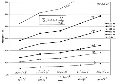 |
The relationship between
surface absorption of sound and RT60 is given by Sabine's
formula and depends on room volume and surface area. The graph shows
the required absorption percentage for five different size rooms when a
certain RT60 is desired. Consider that an open window is 100% absorptive.
So in order to obtain 20% absorption in a room would require that 20% of
its surface area acts like open window. The graph should highlight why it
is very difficult to obtain RT60 values below 300 ms if a room is large.
For other room dimensions see T60-absorption.xls
.
Fortunately a speaker like the ORION works really well in rooms with RT60 around 500 ms which are fairly live and it seems to loose spaciousness in highly absorptive environments. |
Following are some preliminary studies of loudspeaker and standing wave interaction.
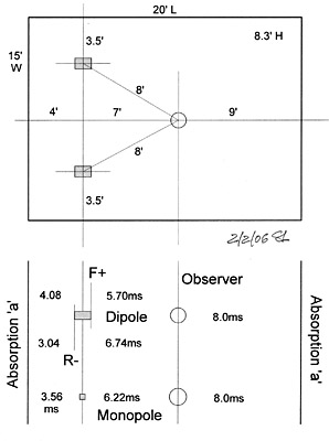 |
On the left is a 300 ft2
room with speaker setup and listener placement as might be used for
critical listening.
Above I looked at monopole and dipole in free space. The next step is to add infinitely large but absorptive walls behind the speaker and behind the listener/observer. The dipole will be looked at as two monopole sources. The sound propagation times from these two sources to the listener and to the walls are shown in the picture as are the times for the monopole. |
Model for wave propagation between two walls.
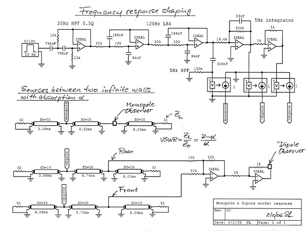 |
The electrical model for analyzing the standing waves between two infinite walls consists of two parts. The first shapes the frequency response of dipole and monopole sources to simulate the ORION. The second part is a transmission line representation of the propagation between the two walls. The lines are terminated by ZL which can be varied according to the desired wall absorption. ZL = Z0 = 10 ohm removes the walls and gives free-space behavior. Each wall can be treated separately. The impulse response is obtained by applying a short duration pulse and using a SPICE analysis of the circuit response. Likewise the frequency response is obtained from sweeping a sinewave generator, in both cases using CircuitMaker. You can experiment yourself with the two files dipole-impulse-2.ckt and dipole-freq-2.ckt . |
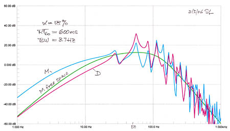
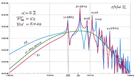
Three cases are investigated having RT60 of 300 ms for a fairly dead room, RT60 of 600 ms for a fairly live room, and RT60 of 5 s for cathedral like reverberation.
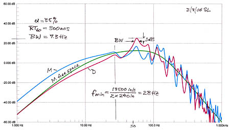 |
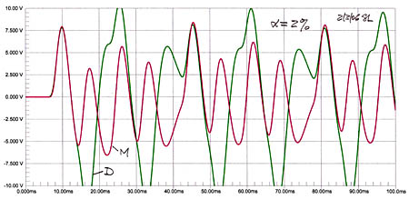
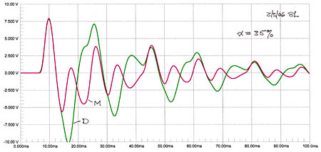 The first 7 ms are identical to the free-space impulse response. |
The lowest mode for the 20 foot distance between the walls is at 28 Hz. Monopole and dipole excite the same axial modes to different degrees but the trend follows the free-space curve of the woofers. Below 28 Hz there is some boost of the monopole while the dipole trends towards the free-space curve.
 |
 |
With lower absorption and longer reverberation time the resonances become larger in amplitude and narrower in bandwidth.
 |
 |
With very low absorption the boost for the monopole below 28 Hz increases while the dipole follows the free-space curve but at a lowered level. Since this model has only two walls the boost for the monopole is underestimated, because the floor to ceiling and side to side axial modes are not included. Those modes would also add more resonant peaks and dips above 28 Hz. The dipole does not radiate in those directions and its response would remain unchanged when the additional walls are added. But both speakers will also excite tangential and oblique modes where the waves are reflected from four and six walls. Things get complicated very fast because nature has no problem to set up these higher modes as I have seen experimentally. Also, rooms are not infinitely rigid, walls flex, reradiate sound and can have resonance amplification and large absorption at very low frequencies, besides having resonances with openings and objects in the room. Sound pressure below the lowest room mode is independent of loudspeaker and microphone position.
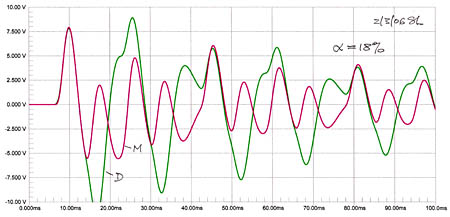
Note that the impulse response of the dipole for the three RT60 values has consistently higher peak to peak variation than the monopole. Whether this is generally true is not apparent and might be the result of the specific configuration that has been analyzed.
----------------------------------------------------------------------------------------
| Page 1 | Page 2 | Page 3 | Page 4 | Page 5 | Page 6 | Page 7 |
|
| ||||


