|

| Introduction |
Specifications | Construction |
Electronics | Supplies | Photos
| PLUTO+ | Pluto-2.1 |
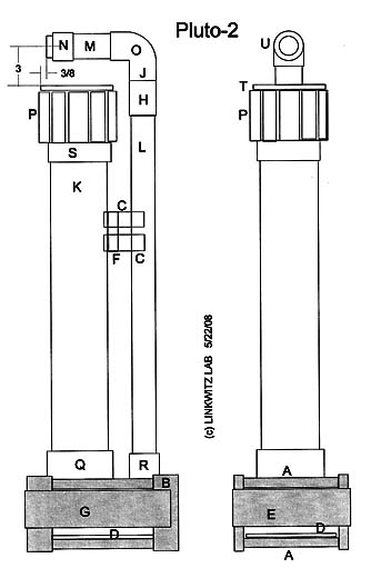
PLUTO-2.1 Construction
The information presented here is supplemental to Revision
4/27/05 of the PLUTO Construction Plans. It provides the necessary
additional detail for constructing PLUTO-2.1. Ignore
the earlier Pluto-2 information on the owner-support page.
A - Replace the
Peerless woofer/midrange drivers with Seas L16RN-SL
(H1480-08) available from www.madisound.com
.
Since the driver has a circular mounting rim it is not necessary to use the
cardboard gasket described on page 11. Stuff the 4" pipe uniformly with
Acoustastuf by adding 85 gram for a total of 200 gram.
The tweeter's surround plane should be set back 3/8 inch from the edge of the
woofer's basket rim.
B -
Crossover/Equalizer/Amplifier electronics
Use the updated material list Pluto-2.1-material list.xls
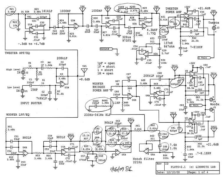
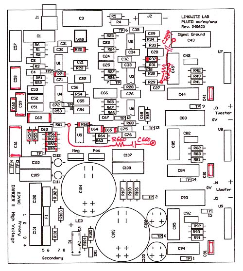
Components with new values and
the two added R-C networks are circled on the schematic and in red on the layout
diagram.
Tweeter channel gain2.1
R21 3.48k
R22 10k
Tweeter high frequency boost
R289 2.87k
C289 2.2nF
Tweeter notch filter2.1
R32 1.00k
Woofer boost
R55, 56 8.25k
R57, 60 12.1k
R58, 59 21.5k
C58 390nF
C59, 62 100nF
C60 open
C61 330nF
Midrange down shelf2.1
R660 1.96k
C660 150nF
Midrange notch filter2.1
R62 2.61k
C64 68nF
C65 150nF
Amplifier stability control
C41, 81, 91 820pF
2.1 = changes
to Pluto-2 |
 |
The leads of C64 and C65 have to be bend so that the two
capacitors fit into the pcb next to each other.
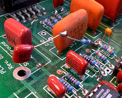
Tweeter high frequency boost R-C network |
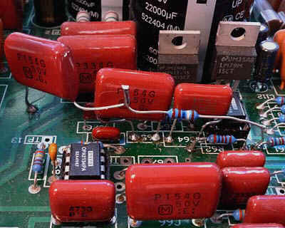
Midrange R-C shelf and notch filter components |
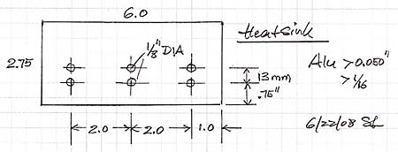
The three power amplifier IC packages are mounted to an
Aluminum sheet metal piece and individual heat sinks. Thermal compound is
applied to the individual heat sinks and the three IC packages. The circuit will
work without the sheet metal heat sink but the amplifiers can get very hot and
shut down protectively at high volume levels. Adding the sheet metal will
increase the amplifier reliability and avoid thermal shut-down.
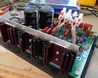
2.0" tall heat sink to fit the original PLUTO base |
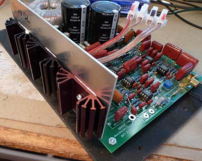
2.75" tall heat sink for the alternative PLUTO-2.1 base |
| The 2.75" height of
the metal piece has to reduced to 2.0" to fit the PLUTO base |
 |
Electrical test chart
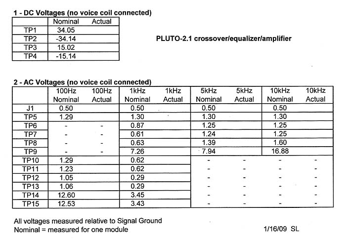
Input
voltages greater that 0.645 V at 10 kHz and above will cause clipping at TP9.
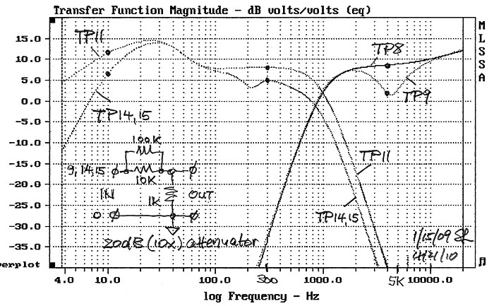
The input to output frequency response without the drivers
connected and measured with a 10x attenuator is the most important description
of the electronic module. It should match within +/-0.5 dB.
The spot frequency checks with the table above are primarily intended to find
errors in construction.
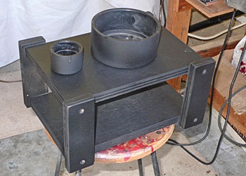
C - Alternative
cabinet construction
A larger base for easier access to the electronic module and improved heat
transfer from the power amplifiers may be desirable.
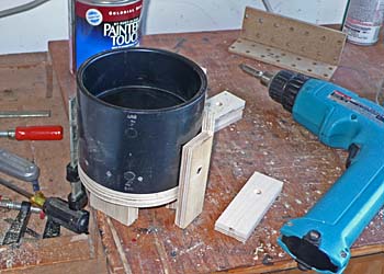
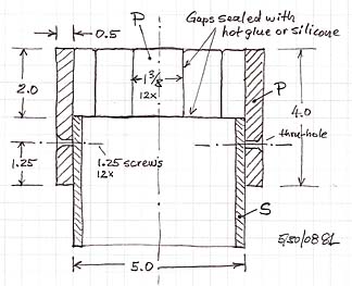
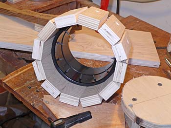
Also the rubber coupler for mounting the woofer/midrange driver can be replaced
by a ring of wood slats that are screwed into a standard 4" pipe coupler.
Place a strip of 3/8" wide and 3/16" thick foam
tape as gasket under the woofer/midrange basket rim before screwing the driver
to the ring of wood slats. The 4" pipe should be stuffed uniformly with 200
gram of Acoustastuf. When upgrading from an existing Pluto-2 it is not necessary
to remove the driver to add stuffing material since the audible effect is
minimal. Check for air leakage by applying a 10 Hz, 10V signal to the
woofer/midrange speaker cable. If you hear puffing noise, then find its location
and seal the leak with GE Silicone II Household Glue. There should be a pin hole
leakage path left open so that the cone comes slowly back out, when slowly
pushed in.
The maximum amount of stuffing material in the pipe behind
the tweeter is not critical, but should be at least as specified.
| Part |
Name |
Material |
Size (inch) |
Quantity |
| A |
Top & Bottom plate |
3/4" plywood |
10.5 x 6.5 |
2 |
| B |
Legs |
3/4" plywood |
5.5 x 2 |
4 |
| D |
Amplifier Mounting plate |
1/4" plywood |
10.5 x 6.25 |
1 |
| E |
Front trim plate |
1/8" hardboard |
8.25 x 3 |
1 |
| G |
Side trim plate |
1/8" hardboard |
10.5 x 3 |
2 |
| C |
Pipe bracket |
5/16' plywood |
3 x 1-3/8 |
4 |
| F |
Pipe bracket base |
3/4" plywood |
3 x 1-7/8 |
1 |
| P |
Barrel plate |
1/2" plywood |
4 x 1-3/8 |
12 |
| S |
4" Pipe Coupler |
ABS or PVC |
5" outside diameter |
1 |
| K |
Woofer pipe |
4" ABS or PVC |
27" long, 4.5" OD |
1 |
| L |
Tweeter pipe 1 |
1.5" ABS or PVC |
30" long |
1 |
| H |
1.5" PVC Pipe coupler |
PVC |
3" long |
1 |
| J |
Coupling insert |
1.5" ABS or PVC |
2" long |
1 |
| M |
Tweeter pipe 2 |
1.5" ABS or PVC |
4.25" long |
1 |
The internal height of the base is 3.5".
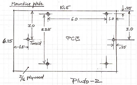 |
Mounting plate for the
electronics Note that the electronic module
described under B above works correctly also for the alternative cabinet
construction.
|
| Introduction |
Specifications | Construction |
Electronics | Supplies | Photos
| PLUTO+ | Pluto-2.1 |
|