
|
|
|
--- The Magic in 2-Channel Sound --- The Importance of Directivity ---
Below is the paper that I wrote for the REPRODUCED
SOUND 2015 Conference of the Institute of Acoustics in the UK.
The Magic in 2-Channel Sound Reproduction
| |||||||||||||||||||||||||||||||||||||||||||||||||||||||||||||||||||||
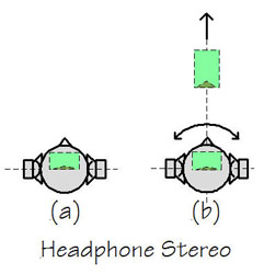 |
Figure 1. Headphone stereo. Localization of the auditory scene inside the head (a), and outside the head when the HRTF of the ear signals tracks with head movement. |
1.2.2
Loudspeaker Stereo
Anechoic, reflection free spaces are essential for loudspeaker measurement and
design; they are also essential to studying directional hearing effects.
For instance, assume that two identical loudspeakers and a listener are
set up in equilateral triangle fashion in an anechoic chamber. Figure 2.
Identical signals are fed to each loudspeaker. If the listener's head had been
blocked - i.e. not allowed to move - and there were no visual cues as to the
loudspeaker location, then the listener hears a phantom source inside his head
between the ears (a), just as with headphones.
If the listener is allowed to turn his head, he then perceives the phantom source in front of him (b2) at approximately the distance to the invisible loudspeakers. For highly directive speakers the center phantom may actually appear in front of the speakers (b1). If the source signal is noise and the listener moves a small distance laterally, then a change in tonality is heard due to changing interference of left and right loudspeaker signals at each ear (c). For greater lateral shifts (d) the signal collapses into the nearest loudspeaker and head turning confirms the location of the physical source of sound.
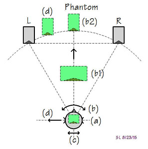 |
Figure 2. Loudspeaker stereo under anechoic conditions. Phantom inside clamped head (a). Externalized phantom with head turning (b). Tonality changes (combing) with small lateral shifts (c). Large lateral head shifts and jumping of phantom to the nearest speaker (d). |
In the recording/mixing process,4,5,6 monaural sources are level panned to locations between the speakers and amplitude and phase differences between the outputs from one or more directional microphone pairs are used to render an acoustic scene between loudspeakers. An off-center phantom source, such as example (d) for a centered listener at (a), can be created by a larger amplitude signal from the left than the right loudspeaker. Below 800 Hz the superimposed loudspeaker signals at left and right ears are converted into timing differences7,8,9,10 between the ears (ITD) as if they were generated from a real source at location (d). Higher frequency content above 2 kHz with larger amplitude from left than right loudspeaker mimics the head shading (IID) effect and stabilizes the off-center phantom. But transient signals can quickly lead to identification of left or right speaker as the real source. It is a task for the mixing engineer to distribute a phantom scene between the loudspeakers. An acoustically dead room is generally preferred as work environment because it allows him to hear more clearly while making decisions. But it is an artificial environment.
2 ROOM RESPONSE
2.1
Room Reflections
While anechoic conditions are useful for studying directional hearing, one
must be careful to translate the findings directly to situations where multiple
reflections of a signal occur. Again, this is a situation that is predominant in
natural hearing and where evolution has optimized the signal processing between
the ears for survival purposes. For example, it is important not to be
distracted by reflections in finding the direction from which a sound is coming.
Psychoacoustic research has shown that a first reflection11, which
occurs shortly after the direct signal (within <25ms), must be stronger than
the direct signal before it shifts the direction of the first arriving signal. A
second12 reflection from a different direction has to be even
stronger than the first reflection to shift direction. But later reflections
(>30 ms) draw increasingly more attention unless their amplitude decreases
with longer delays. This makes sense because late reflections could actually be
coming from a second source.
A loudspeaker in a room produces a large number of reflections13 and perceptual issues become difficult to study in detail because of the large number of signal streams that arrive at each ear of a listener. Figure 3. Matters become even more complicated when the loudspeaker changes polar characteristics with emitted frequency; speaker L is typical for the vast majority of box loudspeakers. These speakers radiate omni-directional at low frequencies and become increasingly more forward directional with higher frequencies while maintaining a flat on-axis response. Consequently such box loudspeaker illuminates the room quite differently from a constant directivity dipole - for example speaker R. The dipole's reflections produce different superimposed sound streams at the ears of a listener even when they arrive from the same directions as those of a box loudspeaker in the dipole's location.
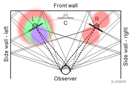 |
Figure 3. Direct signals and some of the reflections at the listener's ears for two types of loudspeakers: Dipole R with frequency independent radiation pattern and typical box loudspeaker L, which radiates omni-directional at low frequencies and becomes increasingly forward directional with increasing frequency. |
Sound from a loudspeaker near the corner of floor and two walls produces at least 7 reflections13. Figure 4. Three of these are first order reflections, three are second order and one is of third order. In reality there would also be ceiling reflections and reflections from a speaker in the left room corner. The direct and reflected signals bounce around in the room building up the sound pressure level (SPL) of the reverberant field and reaching a constant level nearly everywhere in the room if the source signal is sustained in SPL.
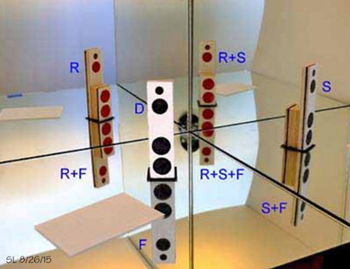 |
Figure 4. A dipole loudspeaker D near the corner of three intersecting surfaces and its images behind the perfectly reflecting surfaces. The images define the direction and the path length of the reflection. In combination with the polar diagram of the loudspeaker and the absorptive/diffusive characteristics of the surfaces the images also define the attenuation of the reflection at any point in front of the loudspeaker. First order reflections S, F, R, second order reflections S+F, R+F, R+S and third order reflection R+S+F. |
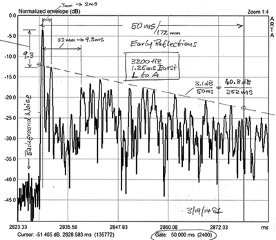 |
Figure 5. Example of a 1.25 ms burst signal and its room reflections as they arrive at the listening position during the first 50 ms. The burst amplitudes are progressively attenuated vs. time as the signal has traveled greater distances and hit multiple surfaces. |
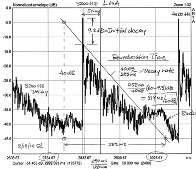 |
Figure 6. As Figure 5 but on expanded time scale to show more clearly the decay of the room reflections of the initial burst signal at the listening position. The 3200 Hz narrow band burst decays 60 dB in 319 ms below the strongest initial reflection. |
Figure 5 and Figure 6 are real world examples giving an indication of the complexities with which the ear-brain hearing apparatus has to deal in order to find the direction and distance of the physical source. Obviously, fewer or weaker reflections make the task easier. With stereo and two loudspeakers we are not interested in the physical sources but the phantom sources and the auditory scene created by the direct loudspeaker signals. So the question becomes how to keep the reflections from becoming a distraction and how to move the room beyond the listener's acoustic horizon of attention.
2.2
Room Resonance Modes
Domestic listening rooms are acoustically small at low frequencies, where their
largest dimensions are less than half of a wavelength. Sustained sounds will set
up standing waves14,15 causing uneven distribution of SPL in the
room. Figure 7. The position of a loudspeaker in the room, its low
frequency radiation pattern, and the sound absorptive characteristics
determine to what degree these resonant modes are excited. Whether the source
radiates omni-directional, like a dipole or a cardioid, the longitudinal mode in
Figure 7 will be set up. Only if the whole rear wall is totally absorptive or
behaves like an open window will there be no standing wave. This is because
there is no reflection back to the front wall. Standing waves are often
problematic, particularly for a loudspeaker,
which radiates more energy at low frequencies into the room than at higher
frequencies like box speaker L in Figure 3. A loudspeaker which is directional
even at low frequencies - like the dipole R in Figure 3 or a cardioid
loudspeaker - changes the coupling to offending modes by turning it.
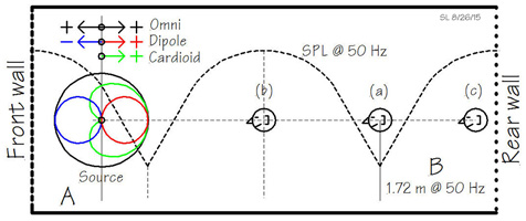 |
Figure 7. Standing wave (room resonance, longitudinal mode) example for a room of 6.88 m length. For a continuous 50 Hz tone listener (a) sits at a SPL minimum, which occurs at 1/4-wavelength from the rear wall. Listener (b) sits at a SPL maximum, but at 25 Hz he would sit in a minimum. Listener (c) against the rear wall is in the maximum SPL region for all room modes. |
Furthermore if the loudspeaker maintains the same polar pattern over the whole frequency range, then energy distribution from low to high frequencies in the room is only a function of the room's absorptive characteristics. Thus, bass from dipole loudspeakers is reproduced with greater articulation16 and more evenness at different listening room locations than from box speakers. By articulation I mean that the envelope modulation of a bass signal is better preserved for different locations in the room. Any ambiance from the recording venue will be heard more clearly because the listening room is illuminated neutrally.
2.3
Reverberated Sound Field
If domestic rooms were simple rectangular boxes with known sound absorption
coefficients for their boundary surfaces and without furniture in them, then it
would be possible to predict14 the large number of modes that could
be excited by a loudspeaker. Table 1. The number of modes 'N' increases
with frequency as does the number of reflections since it takes two or more
boundaries to set up a mode. In the example a) of a room with proportions
deemed
to have acceptable maxima and minima
mode spatial distribution b), there could be up to 55 modes excited by the
loudspeaker below fm = 150 Hz depending upon its placement in the room and its
radiation pattern below 'fm', c). In general, as frequency increases the average
frequency separation of modes 'df' decreases, being down to 1.6 Hz at 'fm'. Each
mode has a 3 dB bandwidth 'bw' and corresponding reverberation time 'T60', which
is determined by the wall absorption properties 'a' at the frequency of
excitation, Table 1 d). A wall or surface absorption coefficient of 25% means
that 1/4th of the room's surface area 'S' acts like an open window for sound to
escape. That is a large equivalent area.
It would have to be increased to 45%
if
a reverberation time of 250 ms were targeted, which is only practically achieved
for this size room by the addition of bulk absorbers and resonant absorbers.
Such short reverberation times are useful for mixing studios with conventional
box type monitors. But for domestic listening and the type of controlled
directivity loudspeakers that I discuss later18, they are not
desirable. I have found a normally furnished room with diffusive and absorptive
elements and a reverberation time around 450 ms to be optimal.
Assuming a 456 ms reverberation time the mode bandwidth 'bw' becomes 4.8 Hz, Table 1e). The bandwidth 'bw' is inverse proportional to 'T60' and is the same over the whole frequency range if the reverberation time is constant.
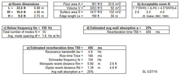 |
Table1. Acoustic properties c) and e) of an unfurnished rectangular room with dimensions a) and estimated wall surface absorption d). |
The modes below 'fs' and the reverberated sound field above 'fs' build up with Trise = 0.32 T60 when sustained acoustic energy is supplied to the room15. It should be noted that 'Trise' is large compared to the duration of high frequency transients, meaning how well transients are heard at different locations in the room depends primarily on the dispersion of the direct sound from the loudspeaker and its reflections.
3 THE MAGIC IN STEREO
3.1
Typical Stereo Reproduction
Domestic listening rooms come in all shapes and sizes and rarely follow the
simple model in Table 1. Except for a few of the lowest order modes and primary
reflection areas, it becomes exceedingly difficult to make predictions
about any room's potential acoustic behavior. Reverberation time is best
measured and gives a general description for different frequency bands. How
useful that is depends upon the loudspeakers that will be installed. I will even
claim that how the room responds to sound is much less of a problem than how the
loudspeaker illuminates the room.
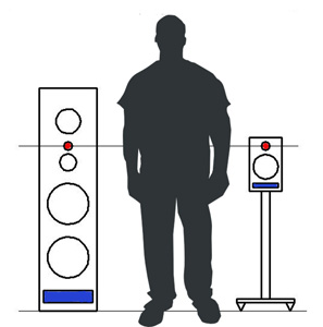
How a loudspeaker will illuminate the room can in most cases be predicted by visual inspection of its shape, its physical dimensions, driver sizes and layout, which all help determine acoustic dimensions and diffraction effects. The vast majority17 of loudspeakers are constructed as rectangular boxes of various sizes, with narrow and tall front baffles, vertically aligned drivers and a vent either in front or in back. The tweeter and the design axis are positioned at seated ear height. Figure 8. There are variations to the front baffle design with rounded edges, a narrower baffle for the tweeter or staggered baffles for "time alignment" of the drivers. The drivers themselves may be vertically aligned as T-W, T-M-W, M-T-M-W or various other configurations including coaxial T-M and W-W on opposing side panels. Regardless, all of these arrangements lead essentially to a horizontal polar pattern as for L in Figure 3 and to a vertical polar pattern that may exhibit lobing determined by the acoustic spacing of drivers and the crossover types used.
The 4ð or "power response" of such speakers always starts out as being omni-directional at low frequencies where its dimensions are acoustically small compared to the radiated wavelength. At the high end the power response ends up to be 10 dB to 15 dB down because any practical tweeter becomes acoustically large and radiates primarily in forward direction regardless of the baffle size. The smoothness with which the power response decreases from low to high frequency has been found to be a strong contributor to perceived sound quality under reverberant conditions. But many loudspeakers seem to have been designed primarily for a flat or slightly down-sloping on-axis response, and sometimes averaged over a specified listening window11. Figure 9.
 |
 |
|
Figure 8. Generic box loudspeakers of various sizes and driver arrangements,
|
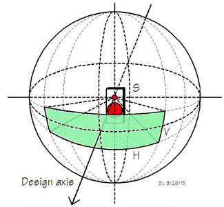
Figure 9. Loudspeakers radiate in all directions to varying degree, but are usually designed and measured for flat on-axis frequency response on a window around the design axis. |
No wonder there is a generic loudspeaker sound. When two of such box loudspeakers are placed in a domestic listening room with all its variations or even when placed in an "acoustically designed" and treated room there emerges a fairly consistent pattern for rendering stereo recordings. Figure 10.
 |
|
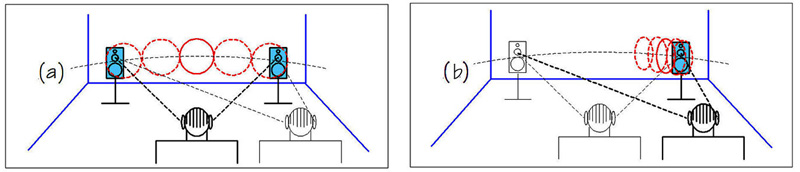
Figure 10. Typical stereo reproduction as heard from the "sweet spot" (a) and from off-center (b). |
Assuming that the loudspeakers are set up symmetrical with respect to the side walls and not against the front wall and that the listener sits at the "sweet spot" - the apex of an equilateral triangle formed by speakers and listener - a phantom acoustic scene is perceived between the two loud speakers (a). The auditory scene (red) is created in the listener's mind based upon the direct sounds coming from the loudspeakers and the reflected and reverberated sounds in the room (blue). The more directional the speaker radiation the more spatially defined the phantom scene becomes horizontally. I call it 'headphones from a distance'. The loudspeakers are clearly perceived as hard boundaries of the scene. There is a distinct awareness of loudspeakers, room and scene (red & blue). The sonic signature of the loudspeaker not being neutral is more to blame for this behavior than the room.
A small lateral shift from the sweet spot shifts the whole auditory scene in the direction of the shift and for a listener off to the side the scene essentially collapses into the near loudspeaker. Little is heard from the other speaker. For highly directional speakers this effect can be reduced to some extent by toe-in.
3.2
Optimal Stereo reproduction
The magic occurs when the loudspeakers seemingly disappear from the sound scene,
to the point where one is inclined to ask: what
are these two contraptions in front of me doing?
Figure 11. All that is perceived is a phantom scene. A scene,
which is not hard bounded by loudspeakers, softly windowed and extends behind
and above the speakers. While there is a sweet spot, namely the apex of an
equilateral triangle, the scene does not collapse into the nearest speaker upon
moving to one side, but stays between the speakers with a perspective similar to
what one would hear at a concert sitting to the side.
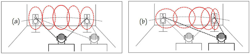 |
| Figure 11. Optimal stereo reproduction as heard from the "sweet spot" (a) and from off-center (b) |
Also, when farther away from the speakers and deep into the reverberant field in the listening room, the tonality does not change. The room is easily forgotten.
The magic is difficult to describe in pictures or words but is recognized within 30 seconds when heard. It usually elicits a big smile or even laughter from the listener. Naive listeners, audiophiles and professionals alike recognize the naturalness of presentation. On many recordings it is 3D in front of the listener and resembles a concert experience. When watching movies on a screen between the speakers, on-screen dialogue and sounds are clearly separated from those off-screen. Center and side speakers are not missed as the two speakers alone render a smooth continuum.
3.2.1
Loudspeaker & Setup Requirements
For the magic to occur there are five requirements,
which
I have found to be essential:
1) The off-axis frequency response of the loudspeaker in the horizontal plane must mimic the on-axis response. The vertical polar response is not as critical but the formation of lobes should be avoided, i.e. the loudspeaker should be acoustically small. Such a loudspeaker has a neutral signature and its reflections and the reverberated sound field will have the spectral signature of the listening room. The polar pattern could be omni-directional, cardioid or dipolar with frequency independent power response. The omni pattern would produce the strongest interaction with the room and be the least desirable of the three.
2) The loudspeakers must be free of resonant radiation such as coming from vents or panels. Non-linear distortion must be low enough not to identify the speaker location during loud music passages. This demands adequate volume displacement capability of woofers and tweeters.
3) The loudspeakers must be set up at least 1 m distance from left and right side walls and 1 m from the wall behind them. The resulting time delay of about 6 ms is necessary for the ear-brain perceptual apparatus to separate direct from reflected sound streams. With neutral excitation of the room response, the listener can then withdraw attention from the room and process primarily the direct sound streams from the loudspeakers. This is similar to not hearing the ticking clock or to the cocktail party effect where attention and hearing is drawn to information streams of interest. Everything else is moved beyond the acoustic horizon as in survival mode.
4) The wall behind the loudspeakers is preferably diffusive and the wall behind the listener absorptive. The sound waves from the loudspeaker should be allowed to travel freely past the listener and not be reflected from a wall behind.
5) The listening room should have a reverberation time around 450 ms, i.e. be neither acoustically dead nor overly live but comfortable for conversation and entertainment. If anything it should err in the direction of liveliness.
4 LOUDSPEAKER DESIGN EXAMPLES
Loudspeakers that fulfill to varying degree requirements 1) and 2) have been available for a long time17. In the dipole family there are the physically and acoustically large panel radiators, for instance from KLH, SoundLab, MartinLogan or Quad. The Quad ESL63 inspired me to find a design that did not suffer from beaming, had extended bass, and was capable of reproducing large dynamics while still preserving the desirable characteristics of the Quad. Omni-directional loudspeakers are exemplified by Ohm Walsh, Bose, German Physiks and MBL; cardioid speakers are available from Gradient, MEG or Kii. Highly directional and efficient speakers were built by Klipsch. The overwhelming mass of loudspeakers sold, though, remains in the box paradigm.
My own loudspeaker designs are first and foremost for use in my own living spaces. Thus I work only under self-imposed constraints in terms of cost, size and aesthetics. A loudspeaker is to me not a piece of furniture but a transducer. As such it has an electrical input and produces an acoustic sound-field as output. I do not sell loudspeakers but offer construction plans for DIY duplication. I like to share what has given me satisfaction and enjoyment. Hopefully my work will have some influence on commercial products.
Figure 12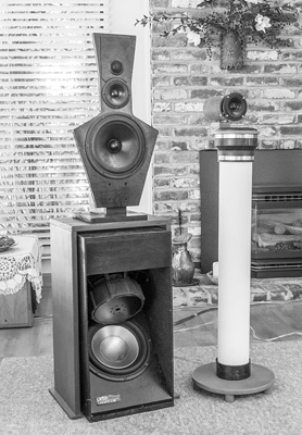 |
Left) LX521.4, a 4-way, full-range (20 Hz to 20 kHz) dipole consisting of three building blocks: 1. An open baffle woofer cabinet with two 10 inch drivers in push-pull arrangement to reduce even-order distortion, 2. A bridge over the woofer cabinet to isolate the open baffle on top from woofer cabinet vibration, 3. A top baffle with 8 inch lower midrange, 3 inch upper midrange drivers, and front and rear side 1 inch tweeters. Electrical crossovers are at 120 Hz (LR4), 1 kHz (LR2} and 7.5 kHz (LR4) |
Right) LXmini, a 2-way (45 Hz to 20 kHz) hybrid polar pattern loudspeaker speaker build up from: 1. An upward firing 5 inch driver in a sealed pipe 2. A forward firing 3 inch full-range driver without baffle and with a scattering body behind it. Electrical crossover is at 750 Hz (LR2). |
Here
then are two recent examples18,19, LX521.4 and LXmini, which, from
the start, were designed with polar pattern and output capability that would be
useful in a wide range of domestic room sizes and also capable of the magic
mentioned above. The first is a full-range dipole, the second a mix of omni,
cardioid, dipole and forward firing radiation. Figure 12.
4.1
Dipole Loudspeaker Design Approach
Having clear objectives of where I intend the speaker to be used and what I want
to accomplish,
my approach to loudspeaker design involves the following steps - usually some of
the steps have to be iterated to arrive at a solution that is satisfactory to
me.
a) First is driver selection for volume displacement capability at low distortion, and small acoustic size for the intended frequency range of use.
b) Next an educated guess has to be made as to the baffle size and shape, which might provide acceptable dipole behavior over as wide a frequency range as possible for each driver.
c) A prototype baffle is built and the polar response is measured in the frontal hemisphere under free-field conditions.
d) The prototype baffle is modified until an acceptable dipole range is found for each driver.
e) Each driver is equalized for flat on-design-axis frequency response and equal output level.
f) The overlap in dipole behavior with the driver below and above in frequency and its volume displacement capability defines the electrical crossover frequency and filter order.
g) With crossovers and equalization active I reverse the polarity of adjacent drivers and adjust the relative electrical signal phase shift or delay to obtain maximum acoustic cancellation at the design-axis measurement point.
h) When satisfied with free-field measurements I listen to a single speaker in monaural in my listening room. I go back to free-field measurements if something seems wrong.
i) I build a second speaker and listen in stereo in my listening room. Adjust woofer level. Go back to free-field measurements if something seems wrong.
Due to the acoustic short circuit between front and rear radiation of drivers on an open baffle it becomes especially important to find a woofer driver which is capable of large excursions without non-linear jumping effects and without air turbulence noise. Figure 13.
4.1.1
Dipole woofer
The woofer’s (2 x 10" drivers) frequency response was measured with the
microphone tip in the center of the opening plane of the woofer’s V-frame
baffle. Figure 14. The baffle sat on the ground to account for half-space
operation. The response exhibits a peak at 250 Hz, which is the result of a ë/4
cavity-length resonance caused by the acoustic wave impedance mismatch at the
baffle opening. The peak is easily equalized. If measured at a large distance,
where front and rear radiation from the baffle combine, the woofer’s response
would decrease at 6 dB/octave rate. Thus to obtain an identical dipole response,
as the one measured in the opening plane, it is necessary to add equalization,
which boosts lower frequencies at 6 dB/octave rate. Additional equalization can
turn the dipole response flat to a target corner. The woofer is crossed over at
120 Hz to a lower midrange driver and operates only in a range where it is
acoustically small.
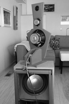 |
Figure 13. Rear side of open-baffle loudspeaker. Sound radiated to the rear is of opposite polarity to sound radiated from the front. The baffle contour and depth defines the path length and thus the amount of phase shift and the degree to which the rear radiation will cancel the sound in the frontal hemisphere. |
4.1.2
Dipolar Lower Midrange
The polar response of the top baffle was measured from 0.5 m distance in the
backyard, being elevated and positioned on a manual turntable. The lower
midrange 8" driver exhibits close to textbook behavior up to about 1 kHz. Figure
15. The baffle shape was determined empirically. Only frontal radiation was
measured. Rear radiation reaches the listener via room reflections and
reverberation, which makes the details of the response much less important. The
total power radiated to the rear is assumed to be similar to the total power
radiated to the front hemisphere.
4.1.3
Dipolar Upper Midrange
The upper midrange driver with its narrow baffle is well behaved above 1 kHz. Figure
16. The response widens between 00 and 300 around 3.5
kHz but is in general quite useable up to 10 kHz. When the upper and lower
midrange drivers are combined with a LR2 crossover at 1 kHz, i.e. a crossover
that is 6 dB down at 1 kHz and provides in-phase addition, then the resulting
overall response indicates dipolar behavior over a very wide frequency range. In
general, it would take many sets of measurements to fully describe the polar
radiation in detail
when
the baffle dimensions and vertical distances between drivers are no longer
acoustically small.
4.1.4
Dipolar Tweeters
Radiation from front and rear tweeters interacts in space forming a radiation
pattern with sound cancellation in the plane of the baffle and a dipole-like
angular dependency. Figure 17. Below 2 kHz the baffle is acoustically
small and a true dipole response results. Above 5 kHz the inherent directivity
of the dome drivers takes over. Front and rear radiation only interact at large
off-axis angles. An LR4 crossover at 7.5 kHz was chosen to combine the
tweeters with lower and upper midranges.
4.1.5
Equalization & Crossovers
Except for the tweeter, extensive equalization is required for the other drivers
to obtain an acoustically flat on-axis response. Figure 18. It would be
impractical to do this with passive, high level networks, though it could be
accomplished with opamp circuitry. The easiest way today is to implement the
filters in DSP and to use individual power amplifiers for each driver.
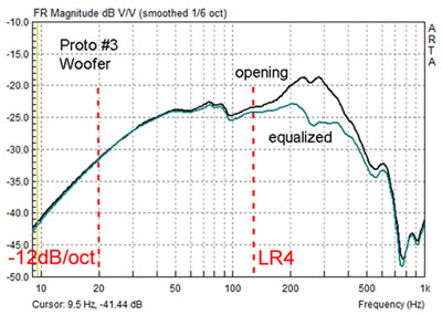
Figure 14. Woofer output before dipole equalization. The V-frame cabinet resonance must also be equalized. |
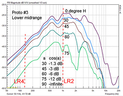
Figure 15. Lower midrange driver (8") in its optimized baffle section |
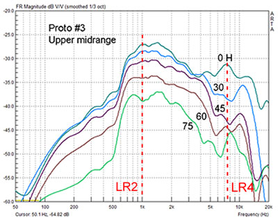
Figure 16. Upper midrange driver (3") in its optimized baffle section |
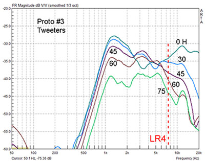
Figure 17. Tweeter drivers (2 x 1") in their optimized baffle section |
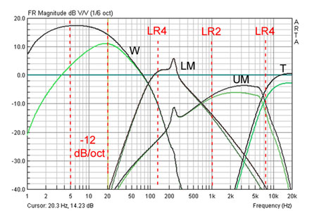 |
Figure 18. Equalization and crossover frequency response as generated by DSP. |
4.1.6
Room Response
Driver centers are vertically aligned along a 1 m line. The loudspeaker's
overall height is 1.25 m. The vertical response around the design axis, which
intersects the top panel between
lower and upper midrange drivers, is typically only optimal over a +/-200
window at the top end of the frequency range under free-field conditions
because
distances between drivers are no longer acoustically small. The wide, cos(á)
dispersion
of individual drivers not only horizontally but also to a high degree vertically
generates spectrally neutral reflections and reverberation. Thus moving about in
the listening room does not change the tonality of sound. Only the preciseness
of imaging changes as the direct-to-reverberant sound ratio decreases with
distance. The minimum distance to the sweet spot is about 2.5 m with the minimum
room volume about 75 m3 to allow for space and breathing room around
the loudspeakers.
4.2
Hybrid Loudspeaker
A physically small loudspeaker like the LXmini 2-way can have a well defined
radiation pattern due to small
baffle areas and driver layout. Figure 19. The upward pointing woofer driver (5
inch) at the end of a sealed pipe radiates omni-directional at low frequencies.
The open baffle full-range driver (3 inch) above it radiates as a dipole. The
combined output of the two drivers in the crossover frequency region takes on
cardioid behavior. A cylindrical scattering body behind the dipole disperses the
rear radiation to minimize specular reflections when the loudspeaker is set up
close to a wall behind it. Bass and full-range sections of the loudspeaker are
acoustically coincident. The combined source is at ear height for a seated
listener and bass is not reinforced by the floor, but immediate surroundings
will have some effect, if they are close - that is unavoidable.
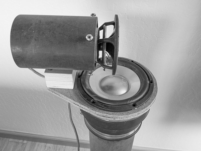 |
Figure 19. Acoustically coincident layout of woofer and full-range drivers and with cylindrical scattering body behind the full-range. |
The woofer's PVC pipe is stuffed with absorbing material. The sound wave traveling down inside the pipe is attenuated and reflected from the sealed end. It is attenuated further coming back up the pipe and through the aluminum cone of the woofer driver so that it is about 40 dB below the radiation coming directly off the front of the cone. The pipe thus acts as an infinite acoustic transmission line with 40 dB return loss. A pipe also has extreme circumferential stiffness so that spurious radiation from its large surface area is completely insignificant. For the critical frequency range up to 1 kHz where the open-baffle full-range driver takes over, the sealed pipe behaves quite differently from a sealed or vented box with its spurious panel vibrations.
The orthogonal arrangement of driver axes, which is unlike a coaxial driver arrangement, should minimize Doppler distortion. But I cannot say how much this contributes to the excellent sound from the LXmini. A pair of these speakers can be listened to as close as from 1 m and is ideal as a near-field monitor or in a small room.
4.2.1
Radiation Pattern
The on-axis response extends from 45 Hz to 20 kHz. Figure 20. The
radiation pattern is essentially rotation symmetrical around the full-range
driver axis. It can be seen that the loudspeaker becomes increasingly more
directional above 1 kHz in the frontal hemisphere as it transitions from
omni-directional through cardoid to dipole radiation. The dipole then
monotonically narrows dispersion due to 3" driver acoustic size. Figure
21.
In the rear hemisphere the radiation pattern goes from omni-directional at low frequencies through a cardioid notch to more or less diffusive radiation above 2 kHz due to the diffracting body, which also adds some amount of attenuation. Figure 22. Overall the loudspeaker has a power response which falls with increasing frequency from 0 dB at the low end to -4.8 dB for cardioid and dipole regions and further due to the increasing directivity of the full-range driver. But unlike a box speaker it preserves much of the rear radiation for the reverberant sound field in the room, which leads to a more neutral tonality. Again, as with the LX521, moving about in the listening room does not change that tonality except when standing close to the LXmini or behind it. From the sweet spot both the LXmini and LX521 sound and image very much alike.
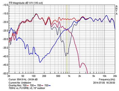 |
Figure 20. Equalized and crossed over frequency responses on full-range driver axis for individual drivers at 0.38 m for normal and reversed polarity of the full-range driver. (Outdoor Measurement contaminated with reflections and low frequency noise) |
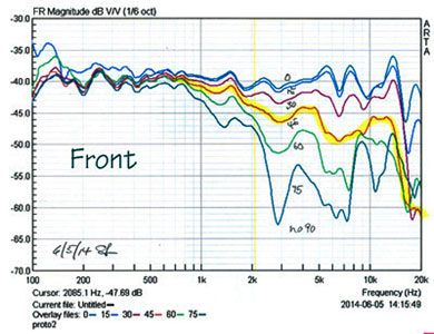
Figure 21. Radiation pattern in frontal hemisphere from 00 to 900 in 150 increments. (+/-450 in yellow) Measured in horizontal plane. |
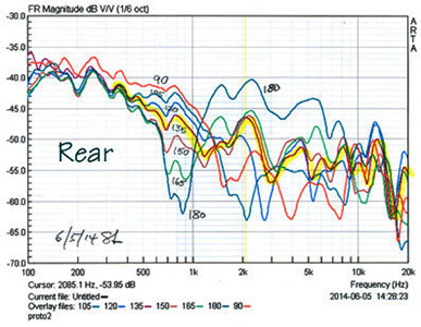
Figure 22. Radiation pattern in rear hemisphere from 00 to 900 in 150 increments. (+/-450 in yellow) Measured in horizontal plane. |
4.2.2
Equalization & Crossover
The woofer driver requires minimal equalization to extend its response to 45 Hz.
Below this frequency it rolls off at 12 dB/octave rate due to the sealed pipe
enclosure. The frequency response shaping is accomplished most easily with a DSP
unit having stereo inputs and four output channels. The full-range driver
requires extensive equalization for a flat output response to 20 kHz. Figure
23. The driver works in break-up mode over most of its frequency range. It
would be difficult and costly to equalize it with passive or active analog
circuitry.
The electrical crossover between woofer and full-range drivers is set to 700 Hz and LR2 with 12 dB/octave filter slopes for wide overlap between the two drivers in order to gradually and smoothly change the radiation pattern from omni-directional to dipolar while going through a cardioid frequency region. Each driver requires its own power amplifier of 50 W to 150 W output capability, i.e. 4-channels of amplification for a stereo setup.
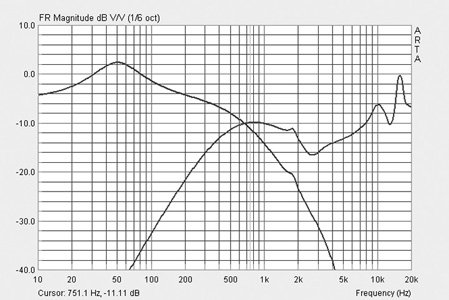 |
Figure 23. Equalization and 700 Hz LR2 crossover for woofer and full-range drivers by a DSP unit. |
The LXmini strikes a remarkable balance between acoustic performance, physical size, bass output and cost. The speaker is at home in any size domestic room. It is well capable of producing the magic which I have described above.
5 THE CHALLENGE
The loudspeaker industry has developed excellent electro-acoustic transducers/drivers over the last 50 years. But when put in boxes of various shapes and sizes in order to send a flat on-axis signal to the listener, illuminating the room neutrally without spurious emissions from the baffle panels has resulted in progress that has been marginal at best.
Actually, the greatest weakness of today's speakers is their acoustic design - I do not need to name manufacturers. Exceptions are rare and their market share is small. Regarding this lack of progress I would also blame equipment reviewers of the various audiophile magazines because in the end, they are the gate keepers and usually beholden to the magazine's advertisers.
If each manufacturer would build a pair of LXmini's as a reference for their product development in order to hear which way they exceed or miss its performance, then real progress might be made. Also, each equipment reviewer should build a pair of LXmini's as a reference for comparing other speakers; this would help to make obvious, in a perceptually meaningful way, the differences between sound systems as experienced in their unique and pictured listening environment. Since it is not difficult nor costly for consumers to DIY build the LXmini as their own reference, they would then know what to expect from a reviewer's description of a different loudspeaker.
I am not saying this because I think the LXmini is the ultimate sound quality reference. Rather, the LXmini defines a standard of excellence that top of the line loudspeakers should meet or exceed before being recognized as a superlative product by reviewers and consumers.
6 REFERENCES
1. A. S. Bregman, Auditory Scene Analysis - The Perceptual Organization of Sound, The MIT Press, 1999
2. L. L. Beranek & T. J. Mellow, "Acoustics - Sound Fields and Transducers", Elsevier-Academic Press, 2012
3. J. Meyer, Acoustics and the Performance of Music, Springer, 2009
4. F. Rumsey, Spatial Audio, Focal Press, 2005
5. H. Wittek, Image Assistant, JAVA applet for determining the "Stereo Recording Angle", www.hauptmikrofon.de
6. SCHOEPS Mikrofone, Showroom, www.schoeps.de/en/applications/showroom
7. B. Rakert, W. M. Hartmann, "Localization of sound in rooms. V. Binaural coherence and human sensitivity to interaural time differences in noise", J. Acoust. Soc. Am., Vol. 128, No. 5, November 2010
8. S. Linkwitz, A Model for Rendering Stereo Signals in the ITD-Range of Hearing, 133rd AES Convention, San Francisco 2012, Preprint 8713
9. E. Benjamin, An experimental Verification of Localization in Two-Channel Stereo, 121st AES Convention, San Francisco 2006, Preprint 6968
10. J. Blauert, Spatial Hearing, The MIT Press, 1997
11. F. E. Toole, Sound Reproduction, Focal Press, 2008
12. P. Damaske, Acoustics and Hearing, Springer, 2008
13. S. Linkwitz, Room Reflections Misunderstood?, 123rd AES Convention, New York, October 2007, Preprint 7162
14. H. Kuttruff, Room Acoustics, John Wiley & Sons, 1973
15. https://www.linkwitzlab.com/rooms.htm
16.
S.
Linkwitz, Investigation of Sound Quality Differences between Monopolar and
Dipolar Woofers in Small Rooms,
105th AES Convention, San Francisco, 1998, Preprint 4786,
17.
The
Absolute Sound's Illustrated History of High-End Audio, Volume 1: Loudspeakers,
Edited by Robert Harley,
Nextscreen, Austin, Texas 2013
18. https://www.linkwitzlab.com/LX521/Description.htm
19. https://www.linkwitzlab.com/LXmini/Design.htm
 |
Baffle Diffraction Versus Presentation at Burning Amp - 2017 |
********************************************************************************************
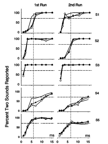
James Heddle commented:
| ... The best
evidence I have found for the ~6msec comes from subjective testing results
shown below (which you may already be aware of) looking at the time window
required for a second sound to be 'defused' from the first.
In addition to this there is now some evidence that the time window before the first reflection also has affects on the perception of the sound stage - localization of the lower frequency audio content improving as the time window increases, i.e. all things being equal, a properly configured system in a bigger room would be expected to have a better sound stage.
Reference: AJ Hill, MOJ Hawksford, |
 |
| One aspect of
this time window I have been thinking about is at low frequency. If it takes in the order of 3-4 cycles to recognize a low frequency tone, as in graph below, then the sound wave has traveled significantly more distance than 2 meters before this occurs. I think this may imply that below a certain low frequency the loudspeakers, and their image sources, will be psycho-acoustically fused not matter what offset from surfaces is in place. Interestingly, I have also seen comments saying that double bass and tuba should be slightly ahead of the beat in musical performances for this reason.
|
|
| James Heddle,
Principal / Managing Director James Heddle Pty Ltd, Acoustical Consultants |
 |
====================================================================================
|
| ||||


