
|
|
|
|
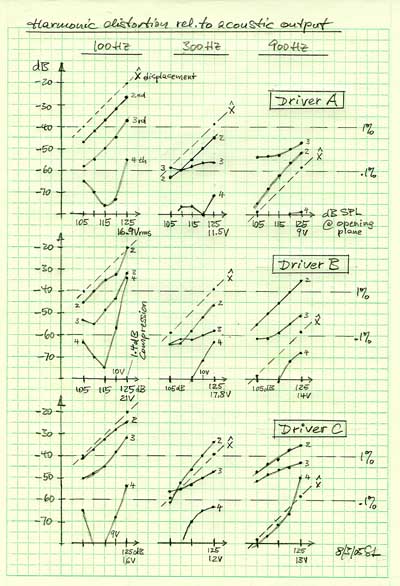 |
Driver A 100 Hz - The relative amplitude change of the 2nd harmonic behaves exactly as expected. The 3rd harmonic starts out with the right slope for high SPL but then decreases more slowly. The 4th behaves strange at low levels. 300 Hz - Excursion x has decreased by 19 dB. The 2nd harmonic follows but not the others. 900 Hz - Excursion x has decreased by 38 dB. The distortion products do not drop correspondingly. Driver B Driver C |
The dominant nonlinear parameters in a driver are the
force factor Bl(x), the stiffness of suspension Kms(x), and the
electrical inductance Le(x). The effect of Bl(x) and Kms(x)
should decrease as 1/w2
with frequency, but since the inductance increases as wLe
its effect should only decrease as 1/w
and possibly overtake the effects of the other two non-linearities. At least
that is what has been suggested to me. All these parameters can be measured with
a Klippel Analyzer, at least
for low frequencies. In the following I will estimate the Le(x)
induced distortion based on measured Le(x) for drivers A and B.
Top
The voice coil inductance changes with displacement x in a nonlinear fashion as seen is the graphs for Driver A and Driver B. The behavior for small excursions around x = 0 can be approximated by the two expressions for Le below.
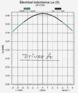
LeA = 410 mH - 70 mH (x / 5 mm)2 |
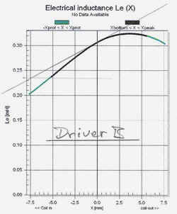
LeB = 305 mH + (70 mH / 7.5 mm) x |
In general, Le(x) can be expanded
as Le(x) = L0 + L1
x + L2 x2 + .... [1]
where L0A = 410 mH,
L1A = 0, L2A = 2.8 mH/mm2
and L0B = 305 mH,
L1B = 9.33 mH/mm
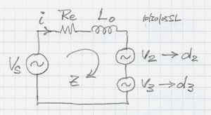
With a current i flowing through the coil the reactive voltage across the inductance Le(x) becomes both a function of i and of resulting displacement x
vLe = Le di/dt + i (dLe/dx) (dx/dt) [2]
The displacement x follows from the relationship between applied force F = Bli and cone acceleration a in the mass controlled region of driver operation far above fs
F = Bli = Mms a [3]
For sinusoidal displacement x = X sin(wt)
the velocity is dx/dt = w
cos(wt) = w
x
[4]
and the acceleration is a = d2x/dt2 = -w2
x
thus Bli = Mms w2
x
and x = Bli / (w2
Mms) = K i [5]
where K = Bl / (w2
Mms)
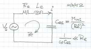
| The current is i = v1
/ Z [6] and for sinusoidal voltage v1 = Vs sin(wt) the current becomes i = (Vs/Z) sin(wt) and thus di/dt = w (Vs/Z) cos(wt) = w i [7] Z = sqrt [ (Re)2 + (wL0)2 ] [8] |
 |
Finally from differentiating [1] above dLe/dx = L1 + 2 L2 x [9]
Inserting [4, 5, 7, 9] into [2] yields the voltage across the inductance
vLe = i wL0 + i2 K wL1 + i3 2 K2 wL2 [10]
Where
i = v1 / Z = (Vs/Z) sin(wt)
i2 = (Vs/Z)2 [1 - 0.5 cos(2wt)]
i3 = (Vs/Z)3 [0.75 sin(wt)
- 0.25 sin(3wt)]
So approximately vLe = i wL0 - 0.5 (Vs/Z)2 K wL1 cos(2wt) - 0.5 (Vs/Z)3 K2 wL2 sin(3wt)
| With a 2nd harmonic
generator v2 = 0.5 (Vs/Z)2 K wL1 and a 3rd harmonic generator v3 = 0.5 (Vs/Z)3 K2 wL2 the relative distortion becomes d2 = v2/Vs = 0.5 (wL1/Z)
(K Vs/Z) [11]
and |
 |
Expressed in dB the distortion is D2 = 20 log(d2) and D3 = 20 log(d3)
Numerical example 1 for f = 900 Hz
| Quantity | Driver A | Driver B | Units |
| Vs | 9 | 14 | Volt |
| Z = sqrt [ (Re)2 + (wL0)2 ] | 6.15 | 6.24 | ohm |
| Vs/Z | 1.46 | 2.24 | A |
| K = Bl / (w2 Mms) | 21.2e-3 | 12.5e-3 | mm/A |
| (wL1/Z) | ---- | 8.46e-3 | 1/mm |
| (wL2/Z) | 2.57e-3 | ---- | 1/mm2 |
| D2 | ---- | -78 | dB |
| D2 measured | -52 | -35 | dB |
| D3 | -118 | ---- | dB |
| D3 measured | -47 | -51 | dB |
| Difference | 71 | 43 | dB |
Clearly there is a huge difference between the distortion estimates and the measured values. The questions is why? The mechanical displacements are extremely small and in the order of 30 micron. The displacements that produce the measured distortion are less than 1 mm. Which nonlinear mechanism is causing the distortion? The currents, magnetic fields, forces and accelerations are the same as at low frequencies for constant SPL, only the excursions are drastically reduced.
There is a second effect due to Le(x) that must be considered which is the reluctance force FL. This force has its useful application in electro-magnetic transducers like door bells and early headphones. Here it is an undesirable remnant. Its magnitude is derived from the energy that is stored in the magnetic field of the voice coil.
W = 0.5 i2 Le(x)
dW/dx = FL = 0.5 i2 dLe(x) / dx
This force will generate 2nd harmonic distortion with an amplitude d2 relative to F = Bli
d2 = FL / F = 0.5 i [dLe(x) / dx] / (Bl) [13]
Numerical example 2 for f = 900 Hz
| Quantity | Driver A | Driver B | Units |
| dLe(x) / dx | 0 | 9.33 | mH/mm |
| i | 1.46 | 2.24 | A |
| Bl | 6.9 | 4.5 | N/A |
| D2 | - infinity | -53 | dB |
| D2 measured | -52 | -35 | dB |
| Difference | infinity | 18 | dB |
For Driver A the gradient of Le(x) is zero and thus this type of distortion is zero. For Driver B the calculated distortion is still by an order of magnitude lower than the measured value. Thus I draw the conclusion that in these two cases the reluctance force is not the dominant factor.
Estimates 1 and 2 do not mean, though, that Le(x)
is insignificant for distortion at high frequencies. They only mean that for a
high frequency excitation signal, with its very small voice coil displacement x,
there is no significant amount of harmonic distortion generated. But, if a low
frequency signal is present together with the high frequency signal, then the
large low frequency voice coil displacements can cause large amounts of
intermodulation distortion products near the high frequency signal due to the
large low frequency variation of Le(x).
Top
The voice coil inductance changes also as a function of the current flowing through it. The magnetic field strength H(i) that is generated by the voice coil current produces nonlinear increases and decreases mH(i) of the static magnetic bias flux density B that is generated by the permanent magnet. The permeability m of the magnetic circuit changes nonlinearly and with hysteresis losses.
The relationship between magnetic flux F and inductance is F = Le(i) i where F = [ B + mH(i) ] A
A time change in flux generates a voltage v = - dF / dt = - i (dLe(i)/di) (di/dt)
Thus the voltage across the voice coil can be described by
vLe = Le di/dt - i (dLe(i)/di) (di/dt) [14]
where di/dt = wi and i = Vs/Z and thus
vLe = wLe - i2 w dLe(i)/di which contains a 2nd harmonic distortion generator (Vs/Z)2 w dLe(i)/di
Similar to the model for [11] above:
d2 = (Vs/Z2) w dLe(i)/di [15] due to flux modulation
The value of dLe(i)/di is not
known to me for drivers A and B. I have seen data for a driver where the
inductance changed in the order of 3% per ampere without shorting rings and 2%/A
with shorting rings.
For the calculation below I have used a value of 3%/A.
Numerical example 3 for f = 900 Hz
| Quantity | Driver A | Driver B | Units |
| Le | 410 | 305 | mH |
| dLe(i) / di | 12 | 9 | mH/A |
| Z | 6.15 | 6.24 | ohm |
| D2 | - 36 | -35 | dB |
| D2 measured | -52 | -35 | dB |
| Difference | -16 | 0 | dB |
It appears that flux modulation is the dominant mechanism for harmonic distortion at high frequencies in these drivers. Driver A actually has shorting rings and Le(i) could not have changed by more than 0.5%/A in order to match the calculated value with the measurement. That may indicate a really good choice of materials and design.
In summary, the measured values do not seem
unreasonable, but there is certainly room for improvement of drivers B and C.
Top
-----------------------------------------------------------------------
1 - Wolfgang Klippel, "Loudspeaker Nonlinearities - Causes, Parameters, Symptoms", 119th AES Convention, New York, October 2005, Preprint 6584
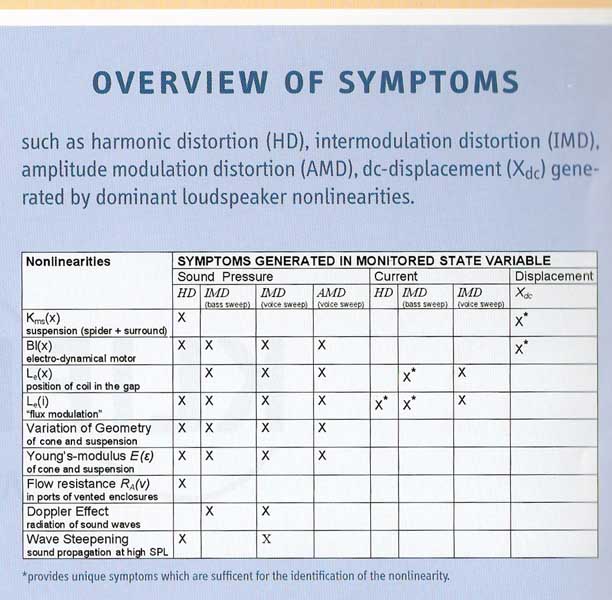
2 - The following two cutouts are from a new and comprehensive poster "Loudspeaker Nonlinearities - Causes, Parameters, Symptoms" by Klippel at CES 2006
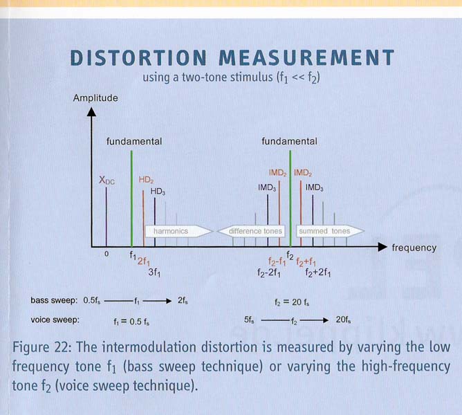
The two stimulus measurement method allows to see and separate out the effects of the dominant driver nonlinearities by measuring distortion in sound pressure, distortion of the voice coil current and dc-displacement.
The table below indicates in which form the symptoms of the nonlinearities show up in the measurements.
3
- "The power of Loudspeaker Models",
W. Klippel, Richard Small, David Clark, Jürgen Ringlstetter, Andrew Bright
Panel Workshop, AES SAN FRANCISCO 2004, Transparencies, PDF
4 - Klippel, "Interactive Listening Test"
5 - Mark Dodd, Wolfgang
Klippel, Jack Oclee-Brown, "Voice Coil Impedance as a Function of Frequency
and Displacement", 117th AES Convention, San Francisco, October 2004,
Preprint 6178
(The effects of impedance variation with current and magnetic hysteresis are not
considered in this paper.)
Other nonlinear and linear distortion measurements and procedures can be found on the following pages:
Audibility of allpass crossover phase distortion
-------------------------------------------------------------------
| Page 1 | Page 2 | Page 3 | Page 4 | Page 5 | Page 6 | Page 7 |
|
| ||||


