
|
|
|
|
| Woofers and subwoofers that
can be placed independently of the main speakers must be integrated
acoustically such that the direct sounds from the different units add
properly at the listening position and yield the desired target frequency
response. The accuracy of integration is strongly influenced by the type
and order of the crossover function and the acoustic highpass response
characteristic of the separate woofer in addition to any difference in
distances from the main speaker and woofer to the listener.
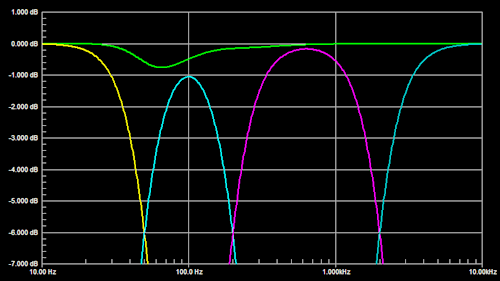
The effects of different crossover functions and offsets will be illustrated for a closed box woofer with F3dB of 30 Hz and Q=0.5 which has optimal highpass transient behavior. The time response, though, will be changed by adding the crossover to the midrange. For a crossover frequency of 100 Hz and a LR2 (-12dB/oct) crossover response the higher frequency output from the woofer is progressively attenuated at 12 dB/oct rate, yet when added to the increasing output from the LR2 highpass filtered midrange, the summed response should give a seamless extension of the main speaker to F3dB and below. Thus the added woofer can extend the frequency range to lower frequencies and also reduce the maximum volume displacement requirement for the midrange driver. |
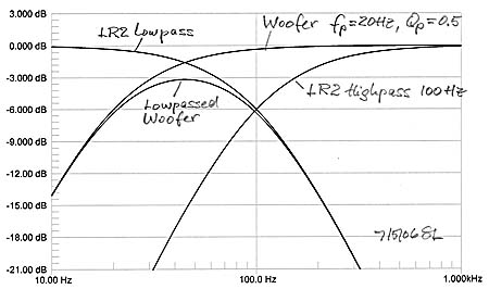 |
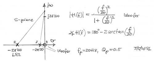
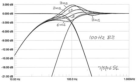
| The woofer highpass response
is described in the s-plane by two negative axis real poles and two zeros
at the origin. It implies a leading phase shift that starts out at +1800
for very low frequencies and which is gradually reduced with increasing
frequency to +230 at 100 Hz. This
phase shift affects the crossover more than the magnitude response of the
highpass which is -0.34 dB at 100 Hz.
Note that for Q = 0.5 the woofer's highpass phase shift response is identical to that of a 1st order allpass with a pole at -20 Hz and a zero at +20 Hz on the real axis. The allpass can be used to compensate the phase lead of the woofer. The radial distance from the woofer to the listener is assumed to be either equal to the distance from the midrange to the listener, or the woofer is further away by 0.5 ms, 1 ms, 2 ms, and 3 ms, where the speed of sound is 0.34 m/ms or roughly 1 foot/ms. |
 |
 |
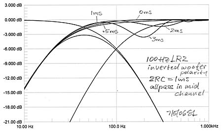 |
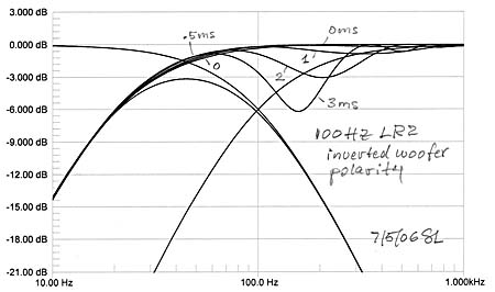
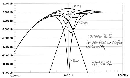
The woofer polarity is inverted for in-phase addition of
woofer and midrange outputs. Not surprisingly the +230 of additional
highpass phase has little influence on the summed response, but anything more
than a foot of path length difference between woofer-to-listener and
midrange-to-listener causes severe dips in frequency response in the two octaves
above the crossover frequency. This can be smoothed out somewhat with added
delay of 1 ms in the midrange channel, but larger amounts of delay correction
require multiple 1st order allpass sections.
In any case, a 2nd order crossover is not very useful for reducing the demands
on midrange driver excursion. Driver cone excursion increases at 12 dB/oct with
decreasing frequency for constant SPL, yet the crossover rolls off at only 12
dB/oct which leaves the excursion constant. The wide overlap of the LR2
crossover leads to increased offset sensitivity above the crossover
frequency.
 |
 |
|
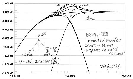
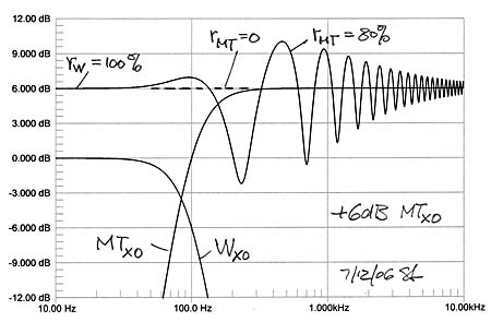
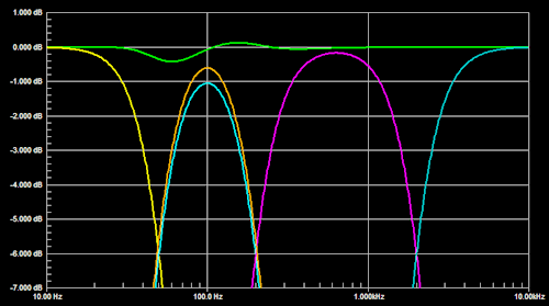
The Butterworth crossovers have 900 of phase shift between lowpass and highpass filter sections at all frequencies, thus the additional 230 from the woofer highpass upsets the proper output addition even when there is no physical offset between woofer and midrange drivers. The woofer's Q = 0.5 highpass phase shift can be exactly compensated by inserting a 1st order allpass into the midrange channel, if the allpass pole and zero are at the same frequency as those of the highpass. Still, the sensitivity to physical offset remains unless it is below 6 inch. A B3 crossover is only marginally useable in our example situation. In general the B3 crossover is problematic because of its high sensitivity to deviation from 900 phase shift between the channels. . |
 |
 |
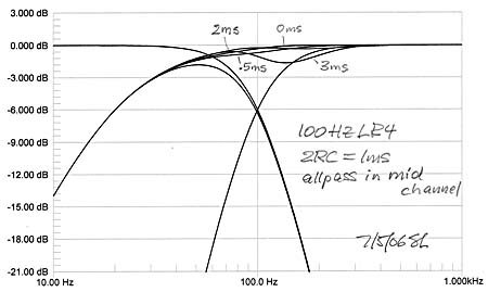 |
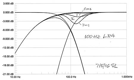
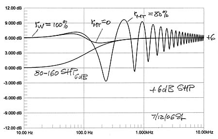
Again, since this is an in-phase crossover the additional highpass phase shift from the woofer has little effect upon the summation of woofer and midrange. Sensitivity to offset is also reduced due to the higher rate of woofer output attenuation, but offset should be kept below 2 feet unless delay compensation is used in the midrange channel. Otherwise the LR4 is a practical crossover for separate woofers.
 |
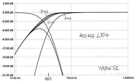 |
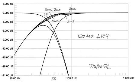
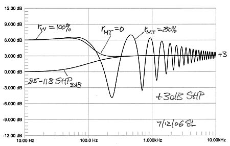
In true subwoofer applications the crossover frequency is usually lower than 100 Hz. In our example the woofer's magnitude response becomes more dominant in addition to its phase response as the crossover frequency moves more into the roll-off region of the woofer. Thus even without physical offset the summed output response is lower than the target. Fortunately this can be compensated quite effectively by increasing the path length to the woofer by up to 3 feet over that to the midrange. The increased propagation loss can be made up by an increase in woofer output level.
If the LR4 highpass response is from an open baffle speaker such as the ORION, then increasing the crossover frequency from 40 Hz to 50 Hz will reduce its maximum excursion requirement for constant SPL by a factor of (50/40)3 = 1.95, i.e. by 6 dB, which can be significant depending upon the application.
Note that none of these physical offset and crossover effects can be sorted out by in-room frequency response measurements of the loudspeaker system. The required measurement time window is too long to reject the room response which tends to dominate the measurement results below 1000 Hz in typical size rooms and for meaningful measurement distances. The analysis here deals with the direct sound or first-arrival frequency response. Included in this analysis is the requirement that the midrange acoustic high pass behavior is either LR2, B3 or LR4 which in practice has to be assured by proper equalization of the midrange channel. Fortunately the low frequency direct sound can be easily modeled, predicted and measured for free-space or half-space conditions. The correlated, but delayed response of the listening room, though, is a different matter. But regardless, it is important to understand and control the behavior of the source of sound in the room if optimum results are to be obtained.
The above analysis gives an indication as to what can be
expected when a commercial subwoofer is added to an existing loudspeaker system,
where the subwoofer roll-off filter is specified but the acoustic highpass
response of the system could be anything. Playing with the subwoofer's roll-off
frequency, its phase shift, polarity, positioning or output level might yield
performance that is adequate for home theater sound effects, but most
likely is not accurate enough for reproducing well recorded music to full
satisfaction.
Top
Adjusting the woofer output level of a loudspeaker based on its anechoic measurement requires some thought when the speaker is later used sitting on the floor, on a stand or with the woofer as a separate unit on the floor. In all cases the presence of the floor will lead to different measurement results than were obtained under anechoic conditions. It should not be concluded, though, that the different measurement result corresponds completely with what we hear. This is again a case were it takes experimentation to know how to translate from the visual data presentation to their auditory significance. Frequency response measurements are one dimensional while hearing has evolved to take its cues simultaneously in time and frequency with importance of one over the other as necessary.
 |
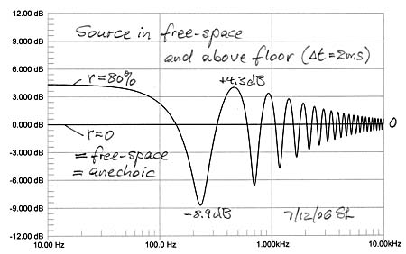 |
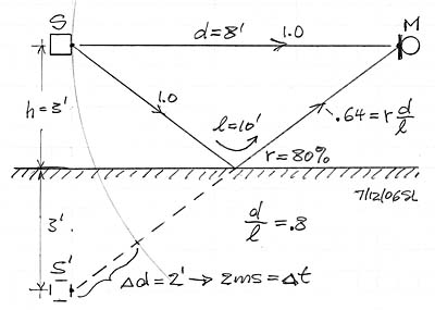
Assume a broadband acoustic point source S in free-space which has a perfectly flat frequency response and a microphone M at some distance d from it which measures the source as having 0 dB output level at all frequencies. When that source S is placed above a very large reflecting surface, then M will measure large ripples in the response due to the addition and subtraction of the reflected and thus delayed sound to the direct sound. If the reflecting surface is the living room floor, maybe carpeted, then it can be assumed that it is somewhat absorptive and dispersive, the more so as frequency increases. In the model above this is indicated by the reduction in floor contribution above 1 kHz. Due to the larger distance traveled by the reflected signal its amplitude is reduced by d/l so that a full +6 dB ripple amplitude is never reached. The interference troughs, though, can be very deep. The first dip in the response is related to the "Allison dip" which also includes reflections off side walls and ceilings. (Roy F. Allison, The Influence of Room Boundaries on Loudspeaker Power Output, JAES, June 1974)
The floor reflection can be perfectly cancelled with DSP for one point in space, and with the potential penalty of creating an incorrect response for every place else. The floor reflection cannot be corrected with a parametric equalizer or a third-octave equalizer because it is an interference phenomenon involving delay. It has been claimed that removing the floor reflection unmasks the true image height information that may be contained in the recorded material. I had an opportunity to test this at the 2006 CES. The recording of Track 4 on the Sound Demonstration CD has a piano up on stage and considerably above the microphone yet relatively close. The Lyngdorf Audio room and floor corrected loudspeaker system placed the piano at tweeter height. Playing the same track on a tall Dali line source speaker without room correction did place the piano at about the elevation angle as it had been heard live.
I am under the impression that we associate the floor
reflection with the height of the playback source above the floor. When you take
a small speaker and place it on the floor so there is no delayed reflection,
then the sound stage also appears to be down on the floor, as if looking down
from the balcony in symphony hall onto the orchestra. Maybe this is the correct
perspective after all since the microphones are usually flown above the
orchestra. Regardless, I prefer my speakers elevated and really dislike the
floor perspective.
Consider also that the floor reflection is an everyday experience, one we have
adapted to since early childhood while its comb filter response has been
changing as we grew
taller.
 |
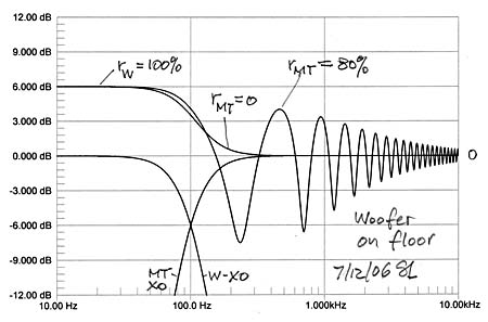 |
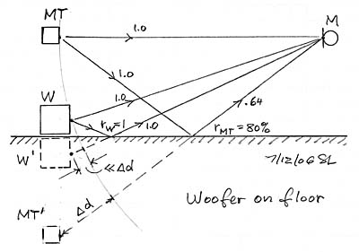
Full range loudspeakers often place the woofer close to the floor which minimized delay of its reflected sound and increases output SPL uniformly by 6 dB over its frequency range. Midrange and tweeter outputs, though, when measured by M are modified by the floor, to the extend that the floor is reflective and the polar responses of M and T lead to illumination of the floor. What should be the target frequency response for designing this speaker when it will be placed similarly in a room? Note that MT reflections could become very small, leading to a frequency response close 0 dB while the woofer W will stay at +6 dB.
 |
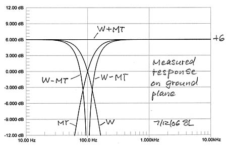 |
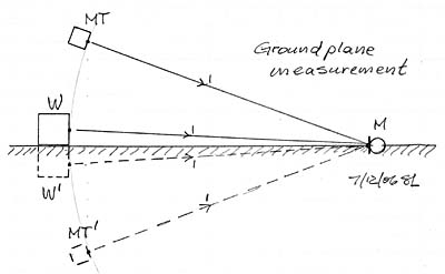
Floor reflections and any other reflections must be eliminated to obtain reliable of measurement data. In the absence of an anechoic chamber or of a very tall tower the best option for low frequency measurements is a ground plane setup of the speakers and with the microphone flush mounted with the ground. Under such conditions one measures the free-space response plus 6 dB, or the half-space response. It is important to measure the crossover frequency response individually for the acoustic highpass, lowpass, sum and difference to ensure reliable data and to understand where the usually present response ripples are coming from, when a large and obstruction free ground plane is not available. Moving or rearranging the setup helps to sort this out. I adjust the drive levels of W and MT for a flat overall frequency response under these ground plane conditions. It gives me a starting response for subjective evaluation of the speaker when set up in my living room. There I can expect the reflection from the floor and also from the walls and ceiling depending on how strongly they are illuminated and how diffusive those surfaces are. Also the room resonances which are set up by multiple reflections between room surfaces will affect the perceived overall spectral balance of the speaker.
I do not measure in the room in order to obtain a flat in-room response, because I have not been able to draw reliable speaker design information from such data. I just do not know the target response for a specific room, speaker and listener placement. If something sounds unusual, I will take the speakers outdoors and try to understand the cause from further measurements under controlled conditions. I find indoor MLS type windowed measurements only reliable for tweeter measurements and maybe for the tweeter to midrange transition. The microphone needs to be positioned far enough from the drivers to also take in cabinet baffle effects. At such distances the reflection free measurement time window becomes typically too short to provide reliable lower frequency information. I have on occasion taken 50 ms long impulse response measurements which take in some of the room behavior and should correlate to perceptual processes, and might point out problem areas, but they are not in my staple of tests, nor are 500 ms measurements which take in the room fully.
 |
 |
|
|
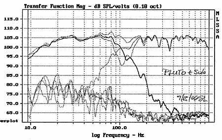
In numerous installations these two open-baffle speaker systems have a balance between their bass and midrange/tweeter output levels that falls within the +/-2.5 dB adjustment range of the woofer level potentiometer. See also the earlier woofer level discussion for the PHOENIX. |
 |
| Recently I designed a
prototype closed box woofer for the omni-directional PLUTO loudspeaker.
The woofer level was adjusted by ground plane measurement for a flat
anechoic response.
Initial listening tests indicated that dropping the woofer level by 6 dB for in-room operation yielded insufficient bass output. Leaving the level at its measured anechoic value is subjectively much closer to being musically correct and maybe only 2 dB too high. What worked for the open baffle speakers does not seem to apply directly to the closed box woofer and omni-directional midrange combination. Thus the question of where to set the woofer level for in-room listening based on an anechoic measurement has no clear and obvious answer in my experience. But without an anechoic measurement there is no absolute reference and no well defined maximum target limit line. Top |
 |
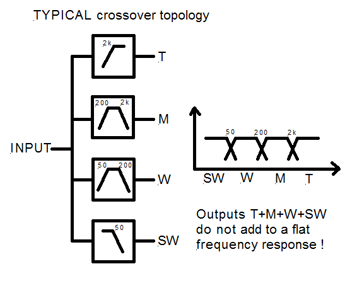
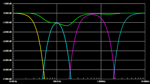
The typical parallel arrangement of crossover filters yields a flat summed frequency response only if the constituent highpass and lowpass filter responses are unaffected by adjacent crossover filter sections. In the example of a 4-way LR4 crossover, the 50 Hz highpass filter introduces a +410 phase error to the 200 Hz lowpass and a negligible magnitude error of -0.034 dB. The 200 Hz lowpass filter subtracts 410 of phase and 0.034 dB of magnitude at from the 50 Hz highpass. But at 100 Hz the 200 Hz lowpass adds 0.43 dB of attenuation to the 50 Hz highpass in the W channel. The 200 Hz highpass filter contributes only +160 of phase to the 2 kHz lowpass and -0.001dB of magnitude. Conversely the 2 kHz lowpass contributes -160 at 200 Hz to the 200 Hz highpass and -0.001 dB magnitude. Phase shift errors are the primary cause for non-flat addition of the filter outputs. These phase errors have less impact upon even-order crossover filters where adjacent channels add in-phase, than upon odd-order crossovers where adjacent channels are 900 out-of-phase.
This parallel filter topology is popular. It is correct for 2-way systems. It usually works for 3-ways when the two xo frequencies are more than a decade apart. It is not appropriate for 4-way systems.
 |
 |
|
The summed response shows less ripple when W and M gains are increased to compensate for phase shift errors. |
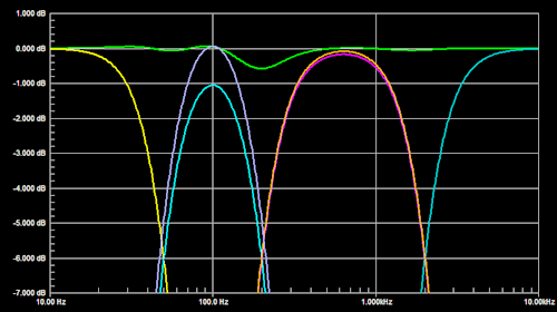 |
In the cascaded crossover filter topology below the +410 phase shift from the 50 Hz highpass at 200 Hz is carried into the 200 Hz lowpass and highpass sections. Thus the 200 Hz crossover filter sections add correctly. But the -410 phase shift from the 200 Hz lowpass at 50 Hz introduces an error to the 50 Hz crossover filter addition. Phase shift from the 200 Hz highpass around 2 kHz is carried into M and T channels. Thus the 2 kHz crossover sections add to flat.
 |
 |
|
The summed response shows less ripple when W gain is increased to compensate for the remaining magnitude and phase shift error. But this is not the complete solution in itself. A maximally flat response is obtained when also the 200 Hz lowpass filter phase shift in the W channel is duplicated in the SW channel by an allpass filter with the same phase response. |
 |
An optimum crossover filter topology should be the starting point when the outputs from multiple drivers with different frequency responses and sensitivities need to be combined for a flat acoustic response. It also applies to the addition of a subwoofer to an existing loudspeaker in order to achieve perfect integration between the two.
Real drivers for T, M, W and SW are not flat from dc to light and must be equalized over the frequency range for which they are to be used. Thus an equalizer block must be provided in each channel. Gain/attenuation must be adjustable to account for differences in driver sensitivity.
Drivers have a low frequency cutoff frequency and are highpass filters by design. The low frequency behavior can be equalized to a certain extent, but the highpass nature remains. It causes a leading phase shift. For example if the SW has been equalized for a 15 Hz, -3 dB cutoff, then this causes phase shift around 50 Hz where the transition to W occurs. Adding an allpass filter in the W-channel with the identical phase shift of the 15 Hz SW highpass provides for correct addition of SW and W acoustic outputs in the 50 Hz crossover region.
The highpass behavior of the W-driver can be imbedded in
the design of the 50 Hz highpass electrical filter so that the acoustic output
follows the targeted crossover filter function. Likewise the M-driver and
T-driver highpass behavior is corrected in the 200Hz and 2 kHz equalizer blocks
to obtain the targeted acoustic response.
The electrical lowpass filter sections in SW, W and M channels may also need
modification, if the drivers have a strong resonance or irregular frequency
response above the filter cutoff frequency. The target is always the correct
crossover filter acoustic response. It may take strange electrical
filters to obtain it.
Finally, the drivers may have acoustical offsets, which can be compensated electrically in the appropriate channels with transmission delay or allpass filters. In the case of allpass filters their groupdelay must approximate the required true delay over a frequency range around the crossover frequency.
F.B.:
Further
thoughts on an "ideal" crossover topology can be found here.
Applications of these principles
can be seen here:
- Analog signal processor - ASP
- THOR-ORION crossover/equalizer
- Separate woofer crossover and offset
- 12dB/oct highpass equalization
- Crossovers
| Page 1 | Page 2 | Page 3 | Page 4 | Page 5 | Page 6 | Page 7 |
|
| ||||


