3 - Acoustics and
Mechanics
3.0
- Introduction
3.1
- Your woofer box
3.2 - Your woofer box at higher frequencies
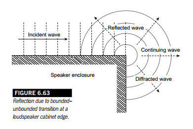
3.3 - Wave diffraction at the cabinet edge
3.4 -
The LXmini woofer
3.5 - The woofer & tweeter combination in Design #3
3.6 - The LXmini tweeter/fullrange
========================================================================
3.0
- Introduction
SL: I will use the Howard
and Angus "Acoustics and Psychoacoustics" book as reference
text.
When I continue with our conversation I will assume that you have read and
understand the material in Chapter 1:
1 - Introduction to Sound
1.1 Pressure waves and sound transmission
1.2 Sound intensity, power and pressure level
1.3 Adding sounds together
1.4 The inverse square law
1.5 Sound interactions
1.6 Time and frequency domains
1.7 Analyzing spectra
I plan to talk with you about sound
radiation into 4p
space, about material in Chapter 6: Hearing music in different
environments, and material in Chapter 7: Processing sound
electronically
So, Fitz, you should get the book:
David M. Howard & Jamie Angus, "Acoustics and
Psychoacoustics", 2006, 2009
Fitz: Will do.
+++++++++++++++++++++++++
HOMEWORK TIME ++++++++++++++++++++++++++++
SL: I am back. It has been
almost 2 months since we talked last. So you had ample time to study
Chapter 1, Introduction to Sound, and we can now get to use what you
learned or what refreshed your memory.
But before we start I must bring up two
more books. The first is:
Zollner, Zwicker, "Elektroakustik", 3. Auflage, Springer,
1993.
It is an excellent book about electro-acoustic engineering fundamentals
and I have not seen anything comparable to this German text book in
English language.
The second book is:
Leo L. Beranek & Tim J. Mellow, "Acoustics - Sound Fields and Transducers",
Academic Press, Elsevier, 2012
It is an update of Beranek's "Acoustics", where Mellow adds the
modern computational expansion and reworking of problems to the classic
reference written by Leo L. Beranek in 1954.
In both books numbers and graphics are used to give meaning to formulas
and their sensitivity to changes in parameters. Engineering always
involves trade-offs and to strike a happy balance between different
requirements. The difficulty in loudspeaker design is to understand how
the ear/brain tolerates acoustic trade-offs. Unfortunately that cannot be
found in either book. But I highly recommend both books to anyone
seriously interested in loudspeaker design.
Fitz: Both books require
too much understanding of math. I am more experimentally oriented and
trust my ears. Also a lot can be learned from discussions on the web.
Besides, I know already what I want to build.
SL: OK, then let's start by
talking about your design. Since you called it #3 I will assume you built
speakers before and have some experience. What information do you have
about the drivers?
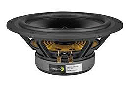
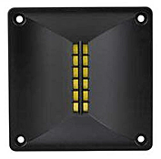
Fitz: Here are the Spec
Sheets for the Woofer
and the Tweeter.
SL: So you mount an
8" driver into a relative small box with about 8 liter internal
volume.
Fitz: Yes, because I want more
bass output than the LXmini can get from its 5"
driver. For the same
cone displacement I should get roughly (8"/5")2 =
2.56 times or 8.2 dB more output because of the larger cone area. I also
chose a sealed box, which means that the low end rolls off at 12 dB/oct.
The LXmini has its -3 dB corner at 45 Hz. I could equalize the 8"
woofer to have its -3 dB corner at (45 Hz) / [sqrt(2.56)] = 28 Hz and have
the same maximum SPL at 28 Hz as the LXmini has at 45 Hz. With DSP it is
easy to extend and flatten the low frequency response.
SL: That is certainly
correct in principle, but lets look a bit more closely at the numbers.
First of all, tell me why you chose a sealed enclosure of that particular
shape and not a pipe like I used for the LXmini.
Fitz: I do not like the
looks and I am in agreement about that with my Domestic Manager, who does
not want to see plumbing parts in our living room.
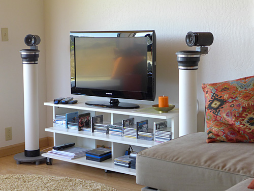
SL: Did you see the Photo
Gallery and what other LXmini builders have done about this?
Fitz: Yeah, but I also
want to try out my own ideas.
SL: OK, then let's look at
your box and woofer selections more closely, to see how they affect
frequency response, how they radiate sound in 3D, how that affects what
you hear in your room.
3.1 - Your woofer
box
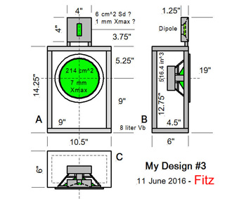
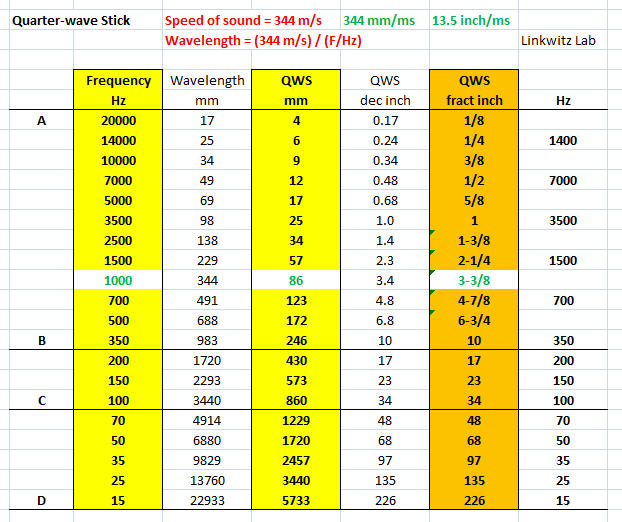
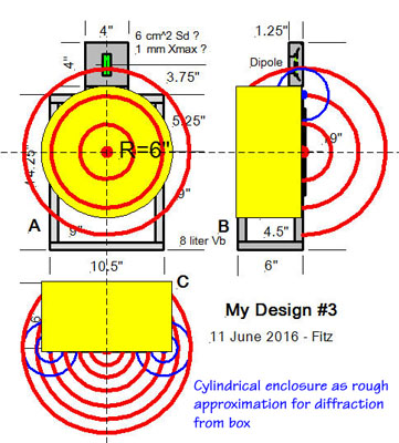
SL: Your Design #3 drawing
gives me the dimensions of the internal box cavity. At low frequencies
where any of its dimensions are small compared to a quarter-wavelength the
air volume acts like a spring. The larger the volume, the more compliant
is the spring. The largest inside dimension is L = 12.75", which
corresponds to a l/4-frequency
Fqw = 13.5"/ms / (4*12.75")
= 0.26/ms = 0.26 kHz = 260 Hz
Fitz: Fortunately I can
get get close enough to that frequency value by reading from your table
and interpolating between 10" and 17" for QWS. I conclude that
the box is acoustically small below 250 Hz.
SL: I understand, but I
need to use some important formulas to tie your woofer
electro-acoustically to your box.
Your box has an internal air volume Vb
of about 8 liter. From the Woofer
Spec Sheet I read that the driver's compliance Cms in free air is equal to
the compliance of air in a box with volume Vas = 56.8 liter. When
you seal your box with the driver's cone, then the combined compliance is
reduced to:
Vtb = Vb*Vas / (Vb + Vas) = 7 liter
The suspension of the driver's cone has
been stiffened. The driver had a free air resonance
Fs = 28.3 Hz = 1 / (2*pi*sqrt(Cms*Mms), which is now increased to a in-box
resonance frequency of:
Fb = Fs*sqrt[1 + (Vas / Vb)] =
80.5 Hz
Likewise, Qts = 0.38 is increased to:
Qb = Qts*sqrt[1 + (Vas / Vb)]
= 1.08
Fitz: What are you trying
to tell me?
SL: Your box volume is too
small for optimum use of the woofer. For example you could double the
internal volume to 16 liter by increasing the outside depth of the box to
10.5". Then you would get:
Fb = 60.4 Hz
Qb = 0.81
Now filling the box with acoustic
stuffing you lower Fb even further (but <18%) to around 50 Hz and bring
Qb ideally down to 0.5 for optimal transient response of your woofer's 12
dB/octave highpass filter response. And you need no DSP to equalize the
low end.
Fitz: Thanks, increasing
the volume is a useful suggestion.
SL: You can learn more
about woofer design from my Thor
project and from the Loudspeaker
System Design pages.
Also, the LXmini low
frequency response design is an evolution from the earlier Pluto
design. In both cases I use a 4" ID pipe. Unfortunately pipes with
exactly the same internal dimensions are often not available outside the
USA.
Fitz: So how much can you
deviate from the original size dimensions?
SL: I will use some
mathematical approximations, which are useful in answering engineering
questions, and which apply when a quantity x is much smaller than 1.
The internal air volume of the pipe Vp
increases as the internal diameter D squared and linearly with pipe length
L.
Vp = L* D2 * pi / 4
The air compliance increases by 10% for a 10% increase in length L and by
20% for a 10% increase in diameter D according to the approximation for
Vpx = L* [D*(1 + x)]2 * pi / 4
(1 + x)2 -->
(1 + 2*x) for x <<1
The air volume affects the resonance
frequency in a square-root relationship: Fb = Fs*sqrt[1 + (Vas / Vb)] :
sqrt(1 + x) --> (1 +
x/2) for x<<1
This means that a 10% increase in pipe
length L decreases the resonance frequency by 5%. A 10% increase in
diameter D decreases the frequency by 10%.
A 10% relative change corresponds to
20*log(1.1 / 1) = 0.83 dB. Hopefully Vp can be held to within 10% of the
design value.
A 12% relative change corresponds
to 1 dB
Fitz: That should be helpful for
LXmini builders and for my own estimations. But I have chosen a box where
you chose a pipe.
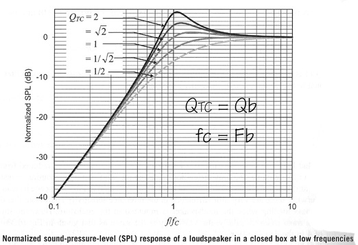
SL: Good that you chose a
sealed box and not a vented box. The graphs here show a comparison between
between a sealed box with Qb = 0.5 and a vented box with the same 50 Hz,
-6 dB corner frequency.
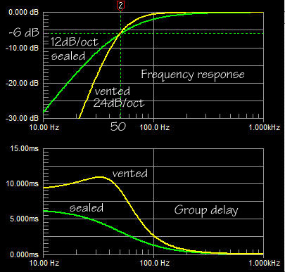 
In a vented box you add a second
resonant structure, which is formed by the compliance of Vb and the air
mass in the vent. The driver&Vb resonator and the Vb&vent
resonator are coupled acoustically. Energy is transferred between them and
used to extend the low frequency response, but at a steeper cut-off rate.
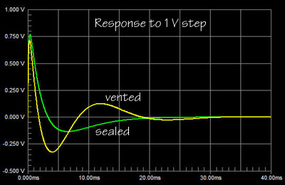
The large amount of stored energy for the vented box is indicated by
the group delay. It leads to ringing in the time domain and a
characteristic bass sound.
Probably 90% of all consumer and
professional loudspeakers are vented. Thus this type of bass coloration
has become the accepted norm and just because for a given box size the -3
dB corner can be pushed down further (increasing the group delay even
more), than when a box is sealed. Bass quantity sells over quality. It's a
male thing.
3.2 - Your woofer
box at higher frequencies
SL: Above 250 Hz, when
your woofer box is no longer acoustically small, then acoustic matters
become more complicated. Radiation from the driver in the box is no longer
omni-directional. Below 250 Hz your woofer acts essentially like a point
source, like a pulsating sphere and it is easy to predict the SPL, which
it will generate in free-space at 1 m distance from the nomograph
below.
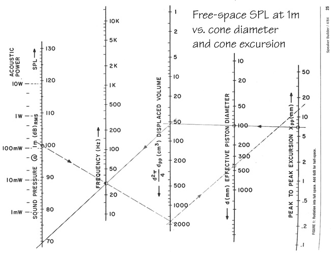
Fitz: Wow, this graph is
like an analog computer and probably from a time before spreadsheets and
computers. If I read it right, then it says that a 100 mm diameter piston
with 3.5 mm Xmax will generate at 30 Hz an SPL of 70 dB at 1 m from the
source. To get 100 dB SPL at 30 Hz would require a 1.8 liter peak-to-peak
displacement. That would be obtained from a 400 mm piston with 7 mm Xmax.
SL: That is correct, but keep in
mind that this is free space SPL. For a woofer you always have a
groundplane, which is acoustically close (<l/4) and you can safely add
6 dB to the SPL number. The woofer radiates only into half-space.
I can also give you a spreadsheet SPL-dependent.xls
into which you can enter your own driver numbers:
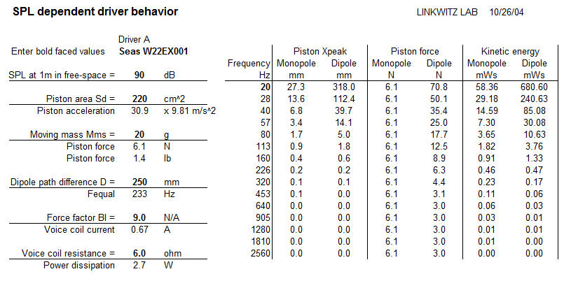
Fitz: I am amazed by the
magnitude of the forces that a driver exerts upon the baffle into which it
is mounted.
SL: Yes, and those forces
transmit a lot of vibration energy into the cabinet, which then flexes the
cabinet walls at their vibration mode frequencies. Small deflections over
a large area can produce more sound output at certain resonance
frequencies than comes originally from the driver cone. I have battled
with spurious radiation from cabinets in my early speaker designs. The
particularly nasty resonances are in the low hundred's of Hz. The only
remedy was to make the cabinets extremely stiff. Using 3/4" plywood
the unsupported panel areas between the braces must not be larger than
4" x 4". Panel vibration modes can occur when the panels are no
longer acoustically small.
Fitz: So my cabinet might
contribute delayed sound radiation at some midrange frequencies to the
intended radiation from the driver's cone?
SL: For sure. Knock on
your cabinet. If it does not ping and hurt, then it is not stiff enough.
Fitz: I guess that I should put
a brace between front baffle and rear wall.
SL: That will help. But
there is more to do. The sound pressure inside the box will be enormous
and also trying to vibrate the walls.
 SPL inside a
box
SPL inside a
box  Distortion of air inside a box
Furthermore there can be air borne
resonances due to the internal dimensions of the cabinet. Stuffing the box
with acoustic absorbent material is essential in order to attenuate
resonances. Their sound is easily transmitted through the thin cone of
your woofer driver.
Fitz: I was going to add
stuffing for sure.
SL: Now let's look at the
dimensions of the woofer box in terms of quarter-wavelengths.
Fitz: Why quarter
wavelengths?
SL: Because when an object
is less than a quarter wavelength in size, then a propagating sound goes
around the object as if it was not there and very little is reflected from
the object. I will explain in more detail how this works.
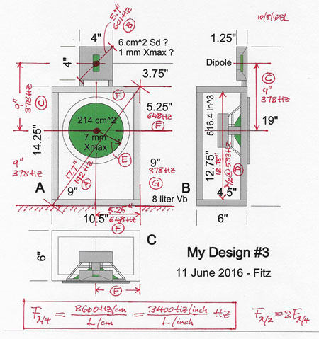
Fitz: I see that you
marked up my drawing with red ink and wrote down the frequency for which a
dimension equals a quarter wavelength.
SL: Look at the front
baffle of the woofer box. The diagonal, the largest dimension of the
baffle, is 17.7" and that equals a quarter wavelength at 192 Hz.
Therefore, roughly speaking, the baffle is acoustically small below
200 Hz and your woofer driver will radiate unimpeded by the baffle into
all directions, like a bare light bulb, which illuminates your room
uniformly.
Fitz: And what happens
above 200 Hz?
SL: That's where it gets
interesting, because now the reflections from the edges of the baffle come
into play. Assume for a moment that the front of your box is just a flat
sheet of wood and that a point source is radiating from the center of your
woofer's location on the sheet. The front of the radiated wave propagates
like an expanding half-balloon until it hits the edge of the the box. As
soon as the half-balloon goes over the edge the volume of air inside the
balloon gets redistributed. The force, with which the balloon surface was
expanding, drops to a lower value. The balloon surface becomes distorted.
Fitz: Yes, I have read
that when the wave comes to the cabinet edge and changes its direction of
propagation in order to follow along the new surface, then that is like
adding a new source at the edge.
SL: It is like the
incident wave comes to the edge and a new source is added, which now
radiates in all directions, which are not bounded by the box surfaces. The
superposition of the original wave with the wave generated from the edge
describes the total radiated sound field.
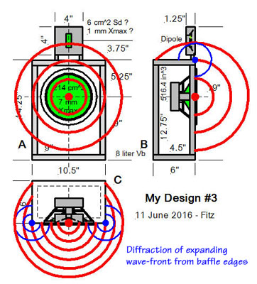
Fitz: The wave-front hits
the 5.5" edges first and the 9" edge last. So there most be a
lot of time smear between the secondary sources along all the edges.
SL: Indeed, it is
difficult to analyze the diffraction from a rectangular box. At this time
my I just want to explain the fundamental principles, which come into play
when we investigate diffraction effects. I will therefore use a 12"
diameter solid cylinder of 6" height with an acoustic point source at
the center to broadly simulate diffraction effects of your box.
3.3
- Wave diffraction at the cabinet edge
SL: First we need to talk
about bounded radiation and free-space radiation, because real acoustic
problems are usually a mixture of both. A woofer box interferes with
free-space radiation from the woofer driver at higher frequencies but not
at the lowest frequencies. And then there is the floor on which the woofer
box sits. The floor stops the wave from expanding.
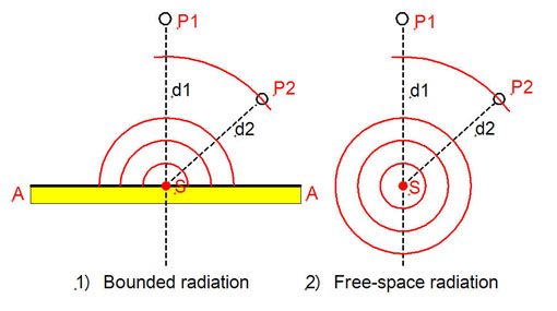
SL: Assume that the point
source S sends out a step in sound pressure and we observe its arrival at
point P1 at distance d1, and which I will call a point
"on-axis". Observation point P2 is off-axis and at distance d2.
Here is what happens for 1) bounded radiation and 2) free-space radiation,
when the two sources have the same strength:
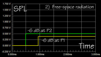
SL: Since d2 is less than
d1 in our example, the step arrives at P2 first. When it gets to P1 the
step is weaker by the ratio of (d2/d1). At a (d1/d2) greater distance the
wave-front also has expanded sideways.
Radiation from the source on top of the infinite boundary can only expand
into 1/2 the space as the unbounded source and will therefore have twice
the sound pressure as the same source radiating into free space.
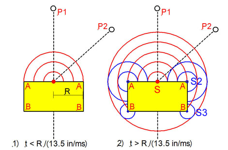
Now let's look at radiation from the
point source S on top of a solid cylinder. A step in sound pressure
propagates out in all directions and along the surface until it comes to
the edge of the cylinder after a time R/c. Added to the original wave is
now the wave from a ring-source S2 due to a change in boundary. Since
space has increased with the right turn of the boundary A-A into A-B the
sound source S2 must cause a decrease in sound pressure. When the original
wave reaches corner B, then a third ring source S3 is superimposed to the
sound field.
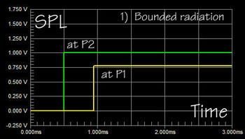
With the observation point P1 a long
distance from the source S and with a pressure step radiated from the
source, you then have the following picture for R = 6":
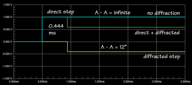
Fitz: I see that with R =
6" it takes 0.444 ms for the step to reach edge A. There a negative
going step is generated due to diffraction. Added to the direct step you
get the green response curve. So at P1 I will see a step that goes to some
amplitude "1" and then drops after 0.444 ms to amplitude
"0.6".
SL: Yes, and if the
cylinder height A-B where close to zero, then the pressure would have
dropped to "0.5". As it is now, there will be another step down
(not shown) when the wave has reached B. From then on the SPl at P1 will continue to
be 6 dB below its initial value.
Now look at the frequency response at
P1 assuming the source S sends out a sinewave of constant amplitude but changing in frequency from 10 Hz to 10 kHz. Look at the response for three
cases. First A-A = infinite, i.e. a very large solid plane. Secondly, A-A
= 12", the cylinder and thirdly, A-A = 0,
or radiation from the point source into free-space.
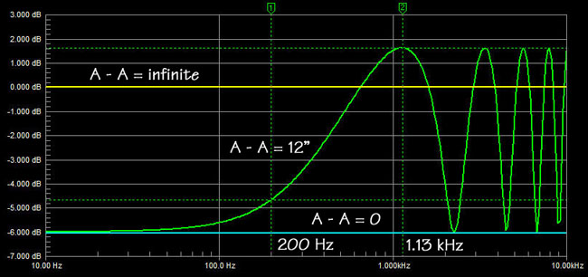
Fitz: So at low
frequencies, below 100 Hz in the A-A = 12" case, the SPL at large
distance from the circular baffle source will be 6 dB lower, than if the
baffle extended to infinity. But as frequency increases the SPL goes up
and reaches a peak at 1.13 kHz. That peak is even higher than if the
baffle diameter were infinitely large. How can that be?
SL: It has to do with the
phase of the reflection at the circular edge A. Look at the time domain
presentation of step response and sinewave response for the 1.13 kHz and
200 Hz cases.
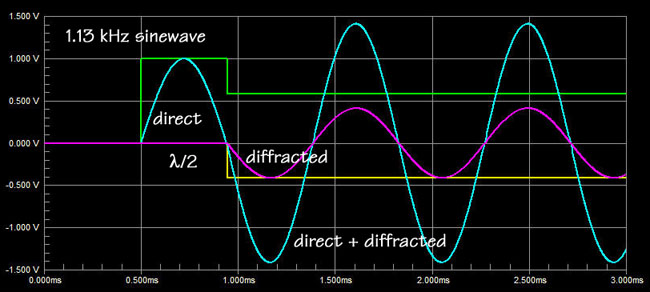
Fitz: I see that the 0.444 ms
delay for the diffraction due to R = 6"
corresponds to half a wavelength or 180 degree of phase shift for a 1.13
kHz sinewave. Thus the diffracted wave now adds maximally to the direct
wave.
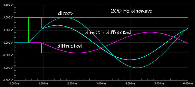
SL: And you can see how at
200 Hz the diffracted wave subtracts vectorially from the direct wave,
because a 0.444 ms delay corresponds to only 32 degree of phase shift.
Fitz: So, the lower the
frequency, the stronger the diffracted wave subtracts from the source
radiation. Diffraction is a side effect of acoustic radiation from a
partially bounded space into a larger space.
SL: Yes, but it could also
be a smaller space. And actually, I have given you only a first order
description of diffraction. I have used an electrical transmission
line model to derive the on-axis, far-field, time and frequency
responses for the case of a point source in the center of a disc with R =
6".
The simple model ignores that the
diffracted wave itself is diffracted again when it travels and encounters
discontinuities in the boundary. And this second order diffraction will in
turn cause third order diffraction effects and so on. Diffraction is
complicated. Browse through the Loudspeaker
Cabinet Diffraction paper, for example.
In the book by Leo L. Beranek
& Tim J. Mellow, "Acoustics - Sound Fields and Transducers",
Academic Press, Elsevier, 2012, Tim Mellow has provided graphs
of diffraction phenomena, which include higher order effects and not just
point sources. For example, taking your 8"
Woofer
but assuming for the moment that it acts like a 6.5" diameter piston
source, then you can see its on-axis frequency response for different size
baffles. I have denormalized ka for a radius of 3.25" so that you
have actual frequency values and may appreciate the practical consequences
of diffraction.
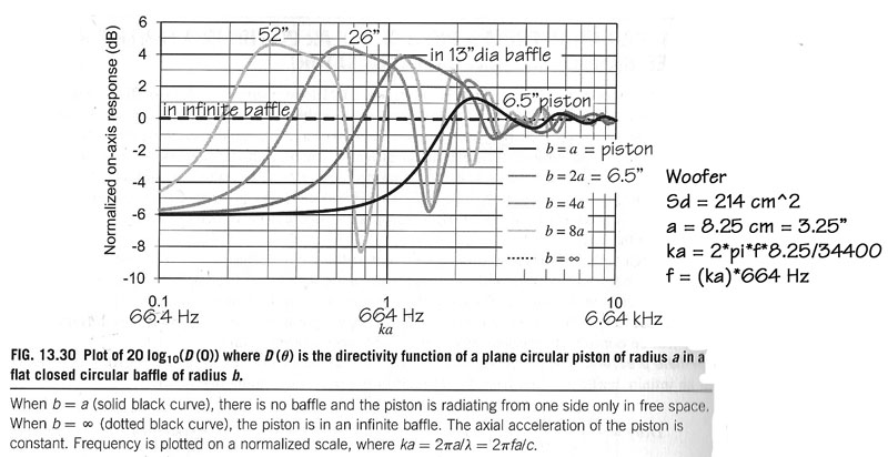
Fitz: I notice that all
the curves go towards -6 dB at low frequencies and wiggle towards 0 dB at
high frequencies. Also the first peak is quite broad. And the dips becomes
less pronounced as the radius of the baffle decreases. The 6.5"
piston acts more like a point source in the 52" baffle.
SL: These curves are for
the on-axis response. You can probably imagine that it is even more
difficult to calculate the off-axis response. Long ago, in 1938,
three Bell Labs researchers, G.
G. Muller, R. Black and T. E. Davis,
published in
"The
Diffraction Produced by Cylindrical and Cubical Obstacles and by Circular
and Square Plates" in The
Journal
of the Acoustic Society of America,
Vol. 10, July 1938, the following graph based on their calculations (which
must have been tedious without modern computers):
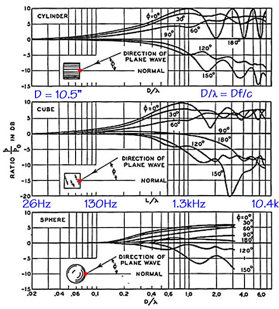
SL: I have denormalized
the frequency axis for the case where D = 10.5". I have then taken
the square box with the point source on one surface and duplicated its
response curves in a spreadsheet for the 0.01 to 1.0 range of D/lambda.
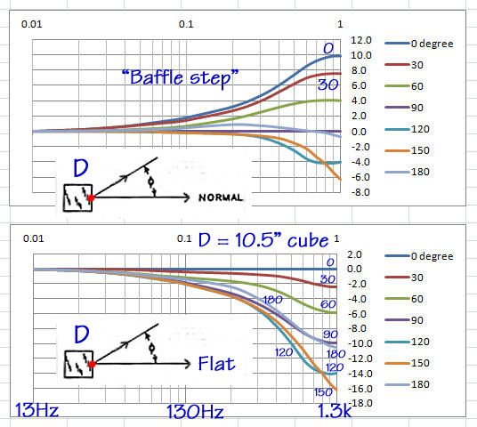
Fitz: So the curves in the
top graph are the same as for the Bell Labs cube?
SL: Yes, as much as I
could read them off of the original. You see that off-axis responses at
30, 60, 90, 120, 150 and 180 degree are all lower than the 0 degree
on-axis response. The rising on-axis response is commonly called the
"baffle step" response. Any respectable loudspeaker designer
will equalize the response to flat. But then hearing the result may tip
down the high end slightly and/or may add a small low frequency bump up.
In my early days of box loudspeaker design I liked a -3 dB/decade down
tilt from 20 Hz to 20 kHz. That gives a gradual and overall 9 dB decrease
in a speaker's on-axis response from 20 Hz to 20 kHz. Movie theaters have
a "House Curve" which drops the high end considerably. These
days I design for plane flat on-axis response in conjunction with flat
off-axis response, where the off-axis amplitude drops the same at all
frequencies.
SL: I side tracked. The
lower of the two graphs above shows the off-axis frequency response when
the on-axis response is equalized to be flat. Notice the similarity
between 90 and 180 degree responses. Notice also that the 120 and 150
degree responses are lower than those. I would not necessarily have
expected that.
Now let's pick five frequencies: 13,
130, 390, 650, and 1.3 kHz, which corresresponds to D/l = 0.01, 0.1, 0.3,
0.5, and 1.0. For those frequencies I have plotted the SPL response as it
would be observed from 0 degree to +180 and to -180 degree. The graph
shows the polar response at the selected frequencies in x-y coordinates.
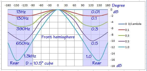
Fitz: It looks that below
130 Hz the response from the point source on the cube is essentially
omni-directional. And with increasing frequency the radiation becomes
increasingly forward directed. But radiation to the rear and particularly
at 180 degree is quite strong, though frequency dependent.
SL: Yes, this "bright
spot" at 1800 is due to the equality of the cube's
surfaces, its edges and symmetry with the 00 axis. The point of
all this diffraction discussion is that a source radiates in all
directions and very much dependent upon its particular shape. The on-axis
response is just one measure. A flat response on-axis is like a necessary
but not at all sufficient condition for a loudspeaker's usefulness in a
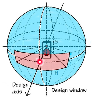
particular setup. Many loudspeaker designers aim for smooth response over
a window area of +/-V vertical degrees and +/-H horizontal degrees, but
those angles are usually chosen far too small to tell a user how the
speaker might sound in her room. She may sit on axis, in the "sweet
spot", but even there it is most likely that more sound, more room
reverberated sound energy gets into her ears than what comes directly from
the speaker on the shortest path to her.
Fitz: I appreciate how sound
coming from all directions affects what I hear. I know the room is always
a problem and I use absorbers and diffusers to make it dead. It works
quite well in my experience. Problem is that the WAF is very low.
SL: So you are aiming for
a sound that I call "headphones at a distance".
Fitz: What's wrong with
that?
SL: It has its place, like
in a recording or mixing studio. But we will get to that later. First I
want to explain the LXmini woofer concept, Why and how it is different
from your woofer in Design #3.
|