|
Amplifiers etc.
+++ Distortion +++ SPLmax
+++ Connections +++ LXmini
+++ LXstudio +++ LX521.4
+++
Amplifier and/or Driver limited Sound
Pressure Level
A) Power amplifier limited SPL of a dipole
woofer
Given two different 10" drivers, and power amplifiers
of 60 W and 180 W capability into 8 ohm, what on-axis, free-space SPL can be
expected at 1 m from a dipole woofer with D = 15" (380
mm) between its front and rear wave exits?
To answer this question I used closed-box1.xls
with the parameter values in the following two tables. The spreadsheet can be
used for dipole speakers by setting the box volume Vb to a value much larger
than Vas and specifying D.
Peerless and Seas drivers:
| Parameter |
10" - XLS
830452 |
10" - W26FX001 |
Units |
Re
Le
Fs
Bl
Qms
Qes
Qts |
3.4
4.3
18.9
17.5
2.63
0.18
0.17 |
6.3
1.43
20
10.7
2.28
0.41
0.35 |
ohm
mH
Hz
N/A
---
---
--- |
Rms
Mms
Cms
Vas |
6.12
135.3
0.52
89.7 |
3.3
60
1.1
161 |
Ns/m
g
mm/N
l |
Sd
Xmax
Sd Xmax |
352
12.5
440 |
330
7
231 |
cm2
mm
cm3 |
ATI power amplifiers:
| Parameter |
AT6012 |
AT1806 |
Units |
P
Vp
Ip |
60
30.9
3.9 |
180
53.5
6.7 |
W
V
A |
| Imax |
7 |
12 |
A (estimated values!) |
For an estimate of the SPL level in the room add 6 dB to
the free-space numbers in the graphs for 2p
radiation, and another 6 dB for the use of two woofer cabinets. If two drivers
are used in each cabinet, and each driver has its own amplifier, then add 6 dB
more for a total of 18 dB. But, if the two drivers are connected in parallel and
driven from a single amplifier, then you can add the last 6 dB only as long as
the amplifier is not limited by its Imax.
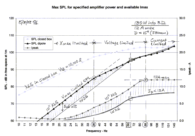
The first graph is for the 180 W amplifier and assumes
that it can deliver almost twice its normal 8 ohm current of 6.7 A into a lower
impedance load. At frequencies below 36 Hz the amplifier can easily drive the
10" XLS to its Xmax of 12.5 mm. Between 36 Hz and 88 Hz the SPL is limited
by the 53.5 V peak swing of the amplifier, and above 88 Hz it is additionally
limited by its 12 A maximum current capability. The W26 driver has 5.6 dB less
volume displacement, Sd Xmax, than the 10" XLS. It also has a weaker motor,
but that is compensated by lower moving mass and higher compliance. The result
it that the SPL is now excursion limited to 66 Hz, albeit at less output than
the XLS. Above 66 Hz the W26 motion is voltage limited. The current never comes
up to its 12 A maximum. Note that above 66 Hz there is little difference in
obtainable output from either driver when used with the 180 W amplifier.
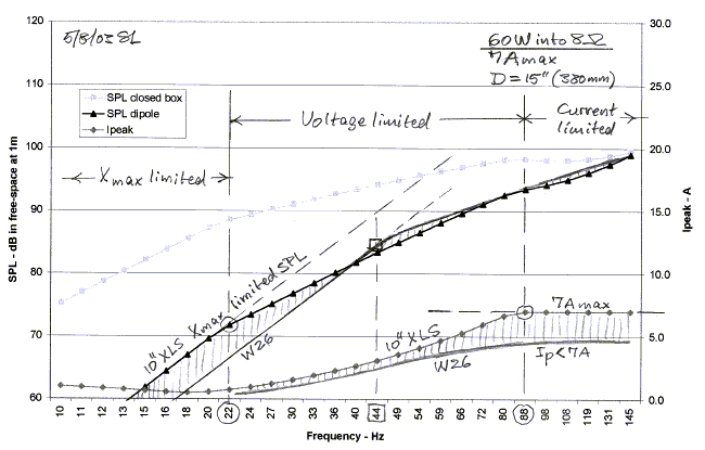
Using the 60 W amplifier with an estimated Imax = 7 A
yields almost identical SPL from the two drivers above 44 Hz, but the level is
about 5 dB = 10 log(180W/60W) lower than for the higher power amplifier. Only
below 22 Hz is the SPL limited by Xmax for the 10" XLS driver. Above 22 Hz
SPL becomes voltage limited up to 88 Hz and current limited above. The SPL from
the W26, by comparison, is excursion limited below 44 Hz and voltage limited
above. Again, as with the 180 W amplifier, the output never becomes current
limited. So if you used the lower power amplifier, then the higher displacement
10" XLS has no SPL benefit above 44 Hz, but below 44 Hz it can provide up
to 5.6 dB = 20 log(440cm3/231cm3) higher SPL. In the case
of the 180 W amplifier the SPL advantage of the XLS over the W26 is below 66 Hz.
The relationship between SPL, driver parameters and
amplifier parameters is complicated as these examples hopefully illustrated.
Each combination of amplifiers and drivers must be analyzed to determine its
sound level output potential. Equalization merely shapes the acoustic frequency
response and gives full use of a driver's
capability.
Amplifier and/or Driver limited Sound
Pressure Level
B) Electrical and mechanical limits
to the maximum sound output from a closed box woofer
I have observed considerable confusion about the power
requirements for a subwoofer. This is not surprising since the interaction
between mechanical and electrical parameters of the subwoofer is complex and
makes general statements very difficult. I will use the example of the THOR
in conjunction with the spreadsheet closed-box1.xls
to illustrate how the power amplifier and the maximum excursion capability of
the driver limit the sound output. A similar analysis has also been done
for a dipole woofer.
The analysis here is for the Peerless XLS 830500 driver, but
any other driver data can be used in the spreadsheet. Alister Sibbald added a driver data base
to the rearranged spreadsheet. Being able to see the graph change as you change
the variables gives better insight into the way the variables interact: Closed-Box-WithDriverDb.xls
In all calculations I use
Xmax = 12.5 mm. Let's start with the driver mounted in a sealed box of 47 liter
(1.7 ft3) internal volume and driven from an amplifier with 75 W
output capability into 8 ohm. For a sinewave signal this corresponds to a 34.5 V
peak voltage and the amplifier, therefore, has probably +/-36 V supply rails.
Depending upon the transformer and storage capacitor sizes in the power supply
the output voltage will not vary significantly when the load impedance is
changed. Ideally this same amplifier would have capability of 150 W into 4 ohm,
and 300 W into 2 ohm. This would mean that the output devices can deliver 4.3 A
peak into 8 ohm, 8.6 A into 4 ohm, and 17.2 A into 2 ohm. In practice the
current capability of the output stage is limited and the 75 W amplifier might
have a spec of 120 W into 4 ohm, not 150 W.
Figure 1 below shows the maximum SPL that the driver could
generate at 1 m in free-space for 12.5 mm peak excursion, and the SPL it
will generate when driven from the 75 W amplifier at different frequencies. The
actual power delivered has the dimension of Volt-Ampere not Watt, since voltage
and current are not necessarily in phase. Starting at low frequencies note that
less than 75 VA is needed to obtain Xmax.
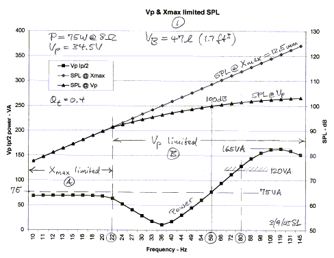
The power drops even further as the 36 Hz resonance
frequency for the driver in the box is approached. Due to the increasing
terminal impedance near resonance the fixed 34.5 V of the amplifier does not
drive sufficient current through the voice coil and the SPL starts to deviate
from the maximum possible. The sound output has become limited by the amplifier
voltage. Above 59 Hz more than 75 VA are consumed as the current increases with
decreasing terminal impedance. Around 80 Hz the 120 W into 4 ohm spec of the
amplifier is reached. At higher frequencies the power demand goes as high as 165
W when the SPL follows the constant amplifier output voltage. The amplifier may
not be capable of this current and the SPL could become current limited in
addition to being voltage limited already.
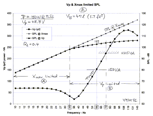
The obvious solution for increasing SPL is to use a larger
power amplifier, Figure 2. Going to an amplifier with 150 W into 8 ohm increases
the output voltage by 3 dB to 48.8 V peak. Correspondingly the available SPL
increases up to 3 dB above 22 Hz. The general shape of the curves is the same as
for 75 W with current limiting potentially controlling the maximum SPL above 72
Hz for an amplifier that is specified at 225 W into 4 ohm.
It is interesting to observe the effects of a smaller
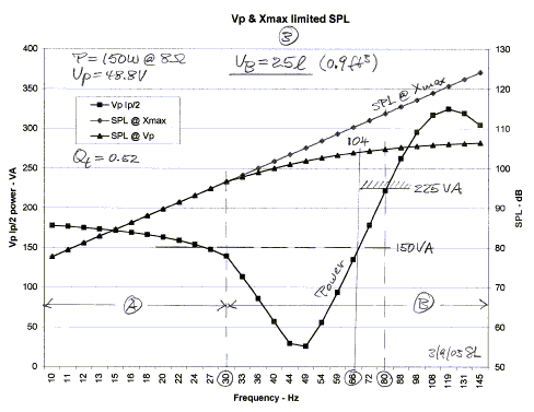
enclosure, Figure 3, and a larger one, Figure 4. Both cases are for a 150 W
amplifier. The resonance frequency increases to around 46 Hz due to increased
stiffness of the 25 liter box volume. This requires more amplifier power below
resonance, but less above it. The maximum obtainable sound output is essentially
identical to the 47 liter box in Figure 2.
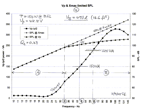
The same driver in a 470 liter box in Figure 4 has its
resonance around 20 Hz and requires little power at low frequencies to reach
maximum excursion of 12.5 mm, but above resonance it takes more power than for
the 25 liter or 47 liter boxes in Figure 3 and Figure 2. The reasons for the
differences in power requirements of the three different box sizes are not
immediately obvious. One cannot make a flat statement saying that a smaller box
requires more power. It depends upon which part of the frequency range one is
talking about. The same goes for the larger box. What can be stated in general
are the following limitations to maximum sound output:
- The woofer's Xmax limits the maximum SPL at the low end
of its frequency range. Amplifier power is rarely an issue.
- Going up in frequency the amplifier is likely to have a
clipped output voltage. The driver impedance is still relatively high in the
frequency region above its mechanical resonance. The voltage, required to
drive the current that is necessary to reach Xmax, is not available from the
amplifier's power supply.
- At the high end of the woofer's frequency range Xmax
can typically not be obtained, because the current that can be delivered is
limited by the safe current capability of the amplifier's output devices and
the power supply's storage capacitors. The driver impedance has a minimum in
this frequency region and even when the amplifier's output voltage is within
its range, the current becomes limited.
The ideal amplifier would have variable supply rail
voltages, so that it can deliver large current when the voltage is low and only
needs to supply high voltage when the current demand is low.
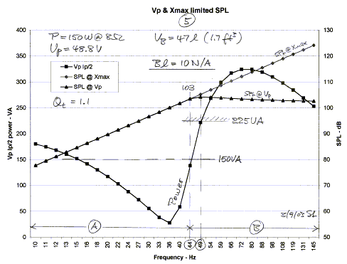
The Peerless XLS drivers have a very strong motor and it
is interesting to see what would happen if the flux density was less, so that Bl
= 10 N/A instead of the specified Bl = 17.6 N/A for the 830500. With all other
parameters unchanged the Qt now increases to 1.1 in the 47 liter box.
Practically at all frequencies more power is required to reach the same SPL as
in Figure 2.
It should be clear from the examples that amplifier power
is not an issue at the low frequency end of the subwoofer range, but at high
frequencies. The lowest frequency output is driver excursion limited. The high
power requirement above resonance is due to the driver's moving mass that must
be accelerated.
Equalizing the frequency response of a woofer with a
"Linkwitz Transform" does not require any
more power over what the driver can handle for maximum excursion without damage.
Such equalization merely makes it easier to run the driver voice coil into its
mechanical stops. Whether such equalization is useful depends solely upon the
driver's volume displacement capability and the desired sound levels.
|